System and method for calibrating a location determined by an inertial navigation unit

Active Publication Date: 2013-03-05
THE BOEING CO
View PDF1 Cites 3 Cited by
  • Summary
  • Abstract
  • Description
  • Claims
  • Application Information

AI Technical Summary

Benefits of technology

[0005]A method, system and inertial navigation unit are therefore provided according to embodiments of the present disclosure in order to facilitate improved location determination. In this regard, the method, system and inertial navigation unit of one embodiment provide for correction of the error associated with the location deter

Problems solved by technology

While the location that is initially determined by an inertial navigation unit may be relatively precise, the error associated with the location that is determined by the inertial navigation unit may gro

Method used


Image

  • System and method for calibrating a location determined by an inertial navigation unit
  • System and method for calibrating a location determined by an inertial navigation unit
  • System and method for calibrating a location determined by an inertial navigation unit

Examples


Embodiment Construction

[0017]Embodiments of the present disclosure now will be described more fully hereinafter with reference to the accompanying drawings, in which some, but not all embodiments are shown. Indeed, these embodiments may be embodied in many different forms and should not be construed as limited to the embodiments set forth herein; rather, these embodiments are provided so that this disclosure will satisfy applicable legal requirements. Like numbers refer to like elements throughout.

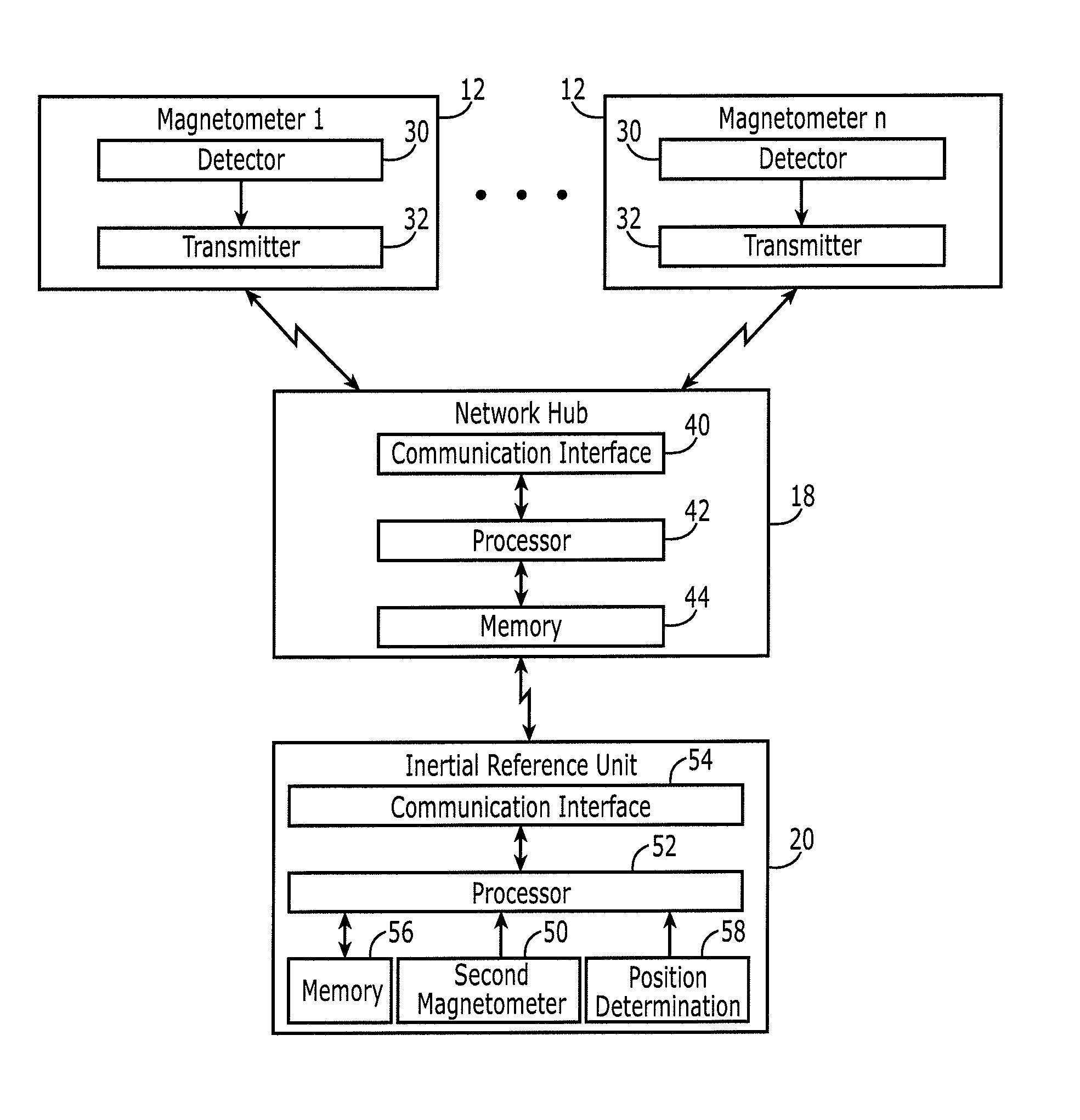
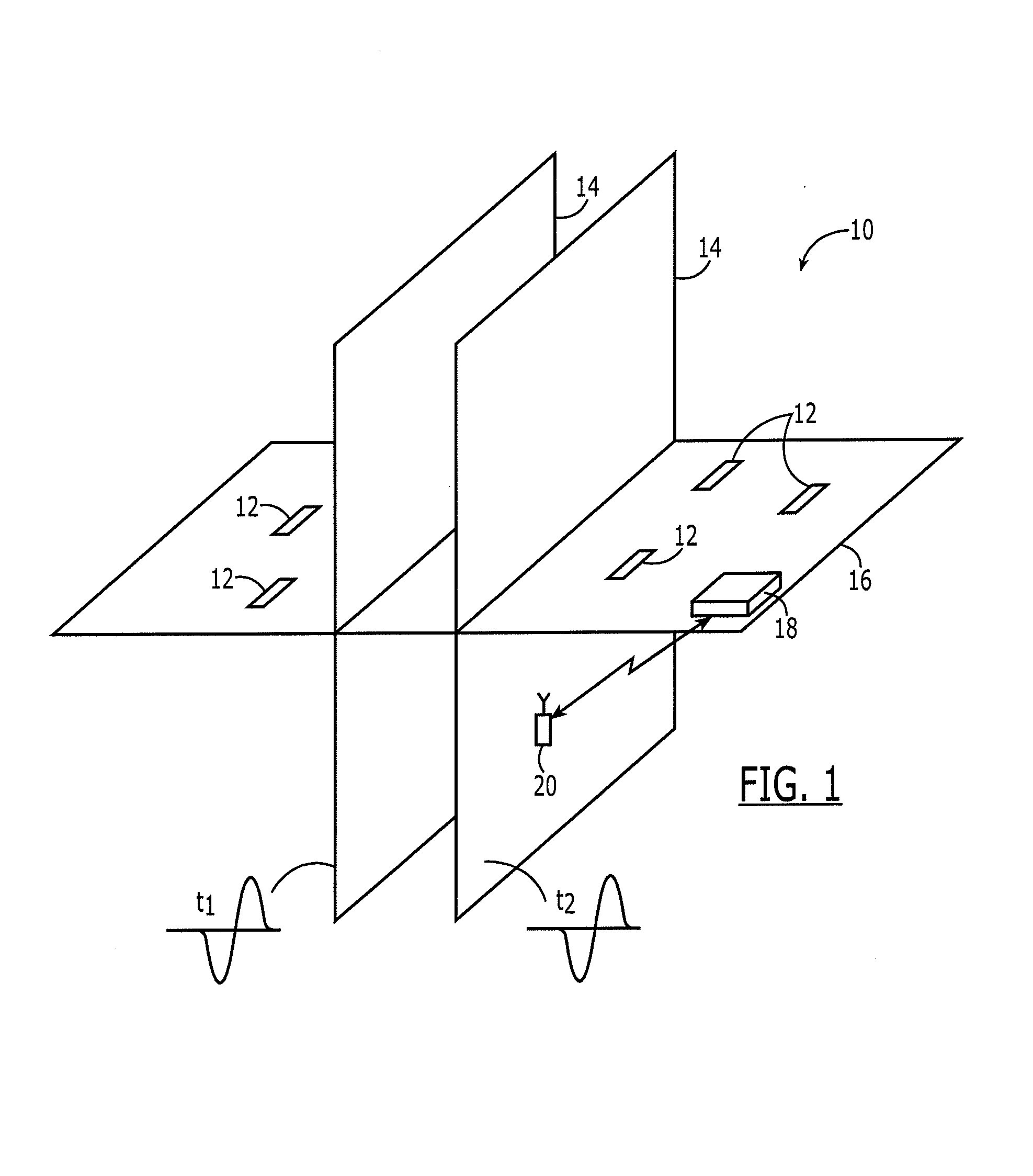
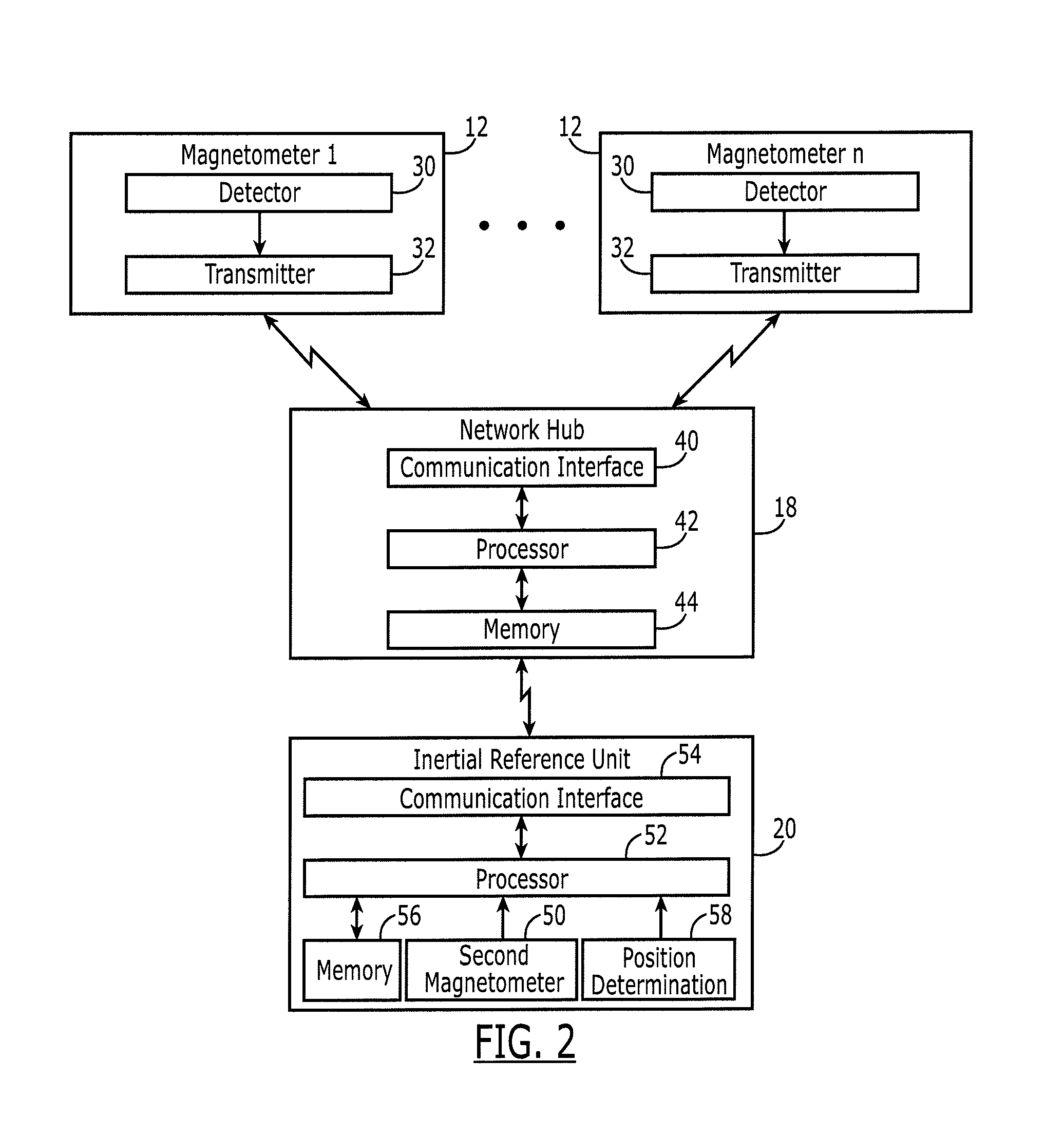
[0018]Referring now to FIG. 1, a propagating magnetic pulse 14 is depicted at time t1 and a subsequent time t2. Magnetic pulses 14 generally propagate outward from an origin or source at a particular velocity. As such, a propagating magnetic pulse 14 may be defined by a wavefront which, in turn, is defined in terms of the position of the magnetic pulse at respective instances in time as represented, for example, by the portions of the wavefront at time t1 and time t2 in FIG. 1. Among other things, the wavefront ...


PUM


Abstract

A method, system and inertial navigation unit are provided in order to facilitate location determination by calibrating a location determined by an inertial navigation unit. The method may receive a magnetic pulse, such as a magnetic pulse generated by a lightening strike, with a plurality of first magnetometers and with a second magnetometer co-located with the inertial navigation unit. The method may also compare a representation of the magnetic pulse received by the plurality of first magnetometers to a respective representation of the magnetic pulse received by the second magnetometer. Further, the method may correct the location determined by the inertial navigation unit as a result of the comparing of the representation of the magnetic pulse received by the plurality of first magnetometers to the respective representation of the magnetic pulse received by the second magnetometer.

Description

TECHNOLOGICAL FIELD[0001]Embodiments of the present disclosure relate generally to the determination of a location by an inertial navigation unit and, more particularly, to the calibration of the location determined by the inertial navigation unit.BACKGROUND[0002]Inertial navigation units may be employed for location determination. For example, an inertial navigation unit may be carried by an individual such that the individual can determine his / her position by reference to the inertial navigation unit. As another example, an inertial navigation unit may be mounted upon or otherwise carried by a vehicle or other structure that is configured to move or be repositioned such that the position of the vehicle or other structure may be determined by reference to the inertial navigation unit.[0003]While inertial navigation units may be widely used on the surface, some inertial navigation units may be deployed in underground applications, such as in underground tunnels, caverns or other sub...

Claims


Application Information

Patent Timeline
IPC IPC(8): G01R33/02G01V3/12G01C19/24
CPCG01R33/0023G01V3/081G01V13/00G01C21/165G01C21/1654
Inventor BARTHOLET, WILLIAM G.
Owner THE BOEING CO
Why Eureka
Try Eureka