
Plasma torch cutting device and process

a technology of cutting device and arc torch, which is applied in the direction of manufacturing tools, soldering devices, auxillary welding devices, etc., can solve problems such as uneven kerfs

Active Publication Date: 2013-03-12
KIFFER INDS
View PDF21 Cites 17 Cited by
  • Summary
  • Abstract
  • Description
  • Claims
  • Application Information

AI Technical Summary

Benefits of technology

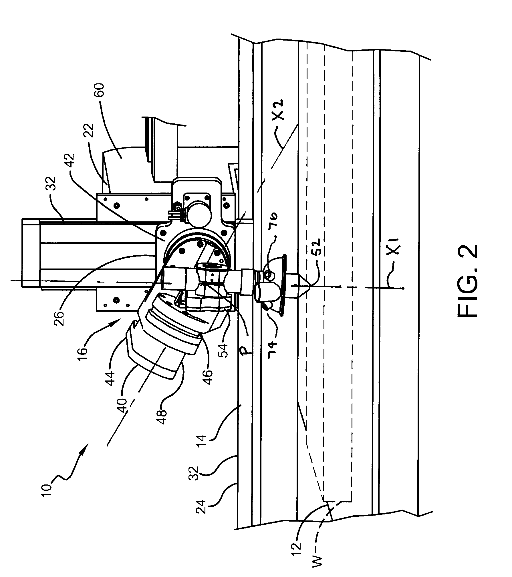
This patent describes an improved plasma arc torch system that can be used for cutting work pieces. The system includes a table for holding the work piece and a plasma arc torch for cutting it. The system also has a positioning apparatus that controls the position and orientation of the cutting torch with respect to the work piece. The positioning apparatus allows the torch to move in five degrees of freedom relative to the work piece. The system also includes a gantry with a traveling beam and a carriage on which the torch is mounted. The carriage is movable along three axes, and the torch can be tilted at an angle relative to themutually orthogonal first, second, and third axes. The system can accurately position the torch to cut the work piece and produce a smooth edge.

Problems solved by technology

However, with some cut geometries, such as circles, prior art positioning systems that control the torch only in mutually orthogonal X, Y, and Z-axes produce a kerf that ends up being uneven as a small portion of the metal remains.

Method used


Image

  • Plasma torch cutting device and process
  • Plasma torch cutting device and process
  • Plasma torch cutting device and process

Examples


Embodiment Construction

[0017]The invention will now be described in the following detailed description with reference to the drawings, wherein preferred embodiments are described in detail to enable practice of the invention. Although the invention is described with reference to these specific preferred embodiments, it will be understood that the invention is not limited to these preferred embodiments. But to the contrary, the invention includes numerous alternatives, modifications and equivalents as will become apparent from consideration of the following detailed description.

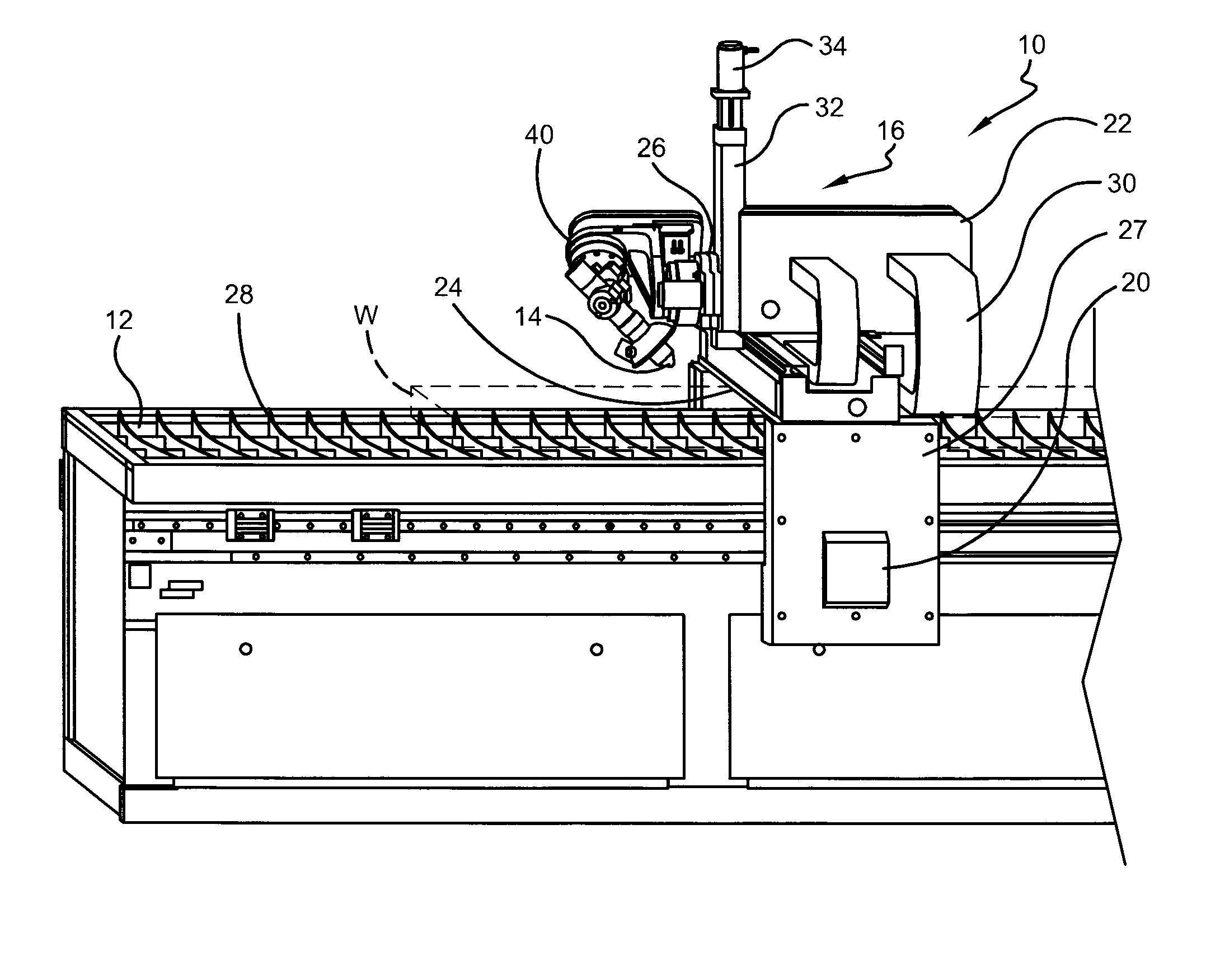
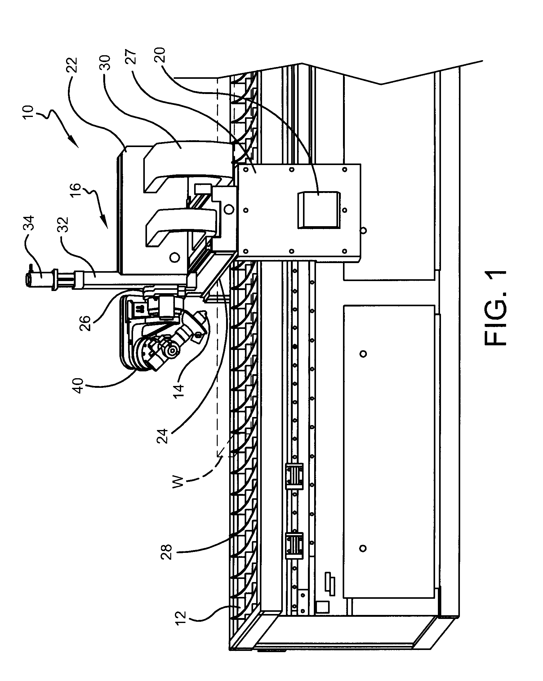
[0018]Referring now to the drawings, FIG. 1 illustrates a plasma arc torch system 10 in accordance with an exemplary embodiment of the present invention. The invention will be described using the plasma arc torch system 10, however, one skilled in the art will understand that the invention may also be used on other cutting systems such as oxyfuel gas cutting systems or laser cutting systems without departing from the scope of the in...


PUM

PropertyMeasurementUnit
angleaaaaaaaaaa
angleaaaaaaaaaa
angleaaaaaaaaaa

Abstract

A method of operating a plasma arc torch system includes placing a work piece to be cut on a table of the plasma arc torch system, wherein at least a portion of the work piece has a planer surface facing away from the table. A plasma arc torch is positioned adjacent the planer surface of the work piece using a positioning apparatus, wherein the positioning apparatus has at least five degrees of freedom about which it can move the plasma arc torch relative the work piece for cutting the work piece on the table. The method further includes angling the torch relative the planer surface of the work piece such that the torch is held at an angle of between about 1 and about 4 degrees from perpendicular with the planer surface to back burn a produced kerf such that a kerf edge is perpendicular relative the planer surface of the work piece. Additionally, the planer surface of the work piece is calculated by contacting the work piece with the torch at least three times.

Description

CROSS REFERENCE TO RELATED APPLICATIONS[0001]This application claims the priority benefit of U.S. Provisional Patent Application Ser. No. 61 / 217,361 filed May 29, 2009 and U.S. Provisional Patent Application Ser. No. 61 / 275,524 filed Aug. 31, 2009.BACKGROUND OF THE INVENTION[0002]1. Field of Invention[0003]The present invention relates generally to plasma arc torch cutting machines and, in particular, relates to a positioning apparatus for positioning the torch.[0004]2. Description of Related Art[0005]Plasma arc torches are widely used for cutting metallic materials and can be employed in automated systems for automatically processing a work piece. The system may include the plasma arc torch, an associated power supply, a positioning apparatus, and an associated computerized numeric controller (CNC). At least one of the plasma arc torch and the work piece may be mounted on the positioning apparatus, which provides relative motion between the tip of the torch and the work piece to di...

Claims


Application Information

Patent Timeline
Patent Type & Authority Patents(United States)
IPC IPC(8): B23K10/00
CPCB23K10/00B23K37/0235B23K26/38B23K7/00B23K37/0241
Inventor PHILLIP, DALE C.MUCKLEY, JAMES P.
Owner KIFFER INDS
Learn More