Grate plate arrangement

a technology of grate plate and grate plate, which is applied in the direction of furniture, lighting and heating equipment, transportation and packaging, etc., can solve the problems of limiting the choice of materials, top walls and front walls that are in constant contact with bulk materials, and are subject to a particularly high degree of wear, so as to achieve simple and precise adjustment of the motion gap

Inactive Publication Date: 2013-03-19
IKN GMBH
View PDF45 Cites 8 Cited by
  • Summary
  • Abstract
  • Description
  • Claims
  • Application Information

AI Technical Summary

Benefits of technology

[0012]The purpose of the present invention is to create a grate plate arrangement for stepped reciprocating grates including a box-like grate plate with a front plate fastened to the front wall in the direction of conveyance, and means for adjusting a motion gap between the front end of the grate plate and the following grate plate in conveying direction, which permits a simple and precise adjustment of the motion gap, and which requires no welds to fix any structural elements, so that on the one hand, non-weldable materials can be used, and on the other hand, non-destructive removal of the structural elements.
[0016]In order to ensure a tilt-free vertical adjustment of the adjustment plate, an additional embodiment of the invention provides means for vertical guidance of the adjustment plate. The guides are on the adjustment plate, on the front plate and / or on the front wall of the grate plate. The guide means permit vertical adjustment, but prevent a lateral displacement or tilting of the adjustment plate.
[0017]To facilitate the assembly of the front plate and the adjustment plate on the grate plate, as well as the adjustment of the adjustment plate for the formation of the motion gap, it is further provided that stop means are provided on the adjustment plate on the one hand, and on the front plate and / or the front wall of the grate plate on the other hand, to limit the vertical displacement of the adjustment plate. This measure allows for loose pre-assembly of the front plate and the adjustment plate away from the step grate, preventing the adjustment plate from dropping out of the top or from the bottom. The actual adjustment and clamping of the adjustment plate can then be done on site, i.e. on the grate plate that forms the grate surface.
[0018]The grate plates are generally arranged with a lateral gap in relation to the adjacent grate plate, to allow for lateral thermal expansion. In an additional embodiment of the invention, to bridge this gap and thus prevent uncontrolled leakage of the cooling air or gas respectively in this way, the adjustment plate projects laterally beyond the width of the grate plate, for example, such that it touches the respective adjacent adjustment plate.
[0019]In an additional structural embodiment of the invention it is foreseen that the front plate is bolted to the front wall of the grate plate by means of a plurality of hexagon socket head fixing bolts, such as Allen screws, the bolt heads of which are located in recesses that are present on the front side of the front plate. Fixing bolts with a hexagon socket head make it possible to provide a cylindrical bolt head that can be received in a circular recess slightly larger than the bolt head, so that the bolt head is largely protected against contact with the bulk material and thus against wear; in this manner, the fixing bolt can also be loosened again with an Allen wrench after extended use.
[0020]The fixing bolts can, for example, be screwed into threaded bores that are formed in the front wall of the grate plate, for example, although this requires appropriate machining of the grate plates. In a preferred embodiment of the invention, the fixing bolts extend through access openings in the front plate and in the front wall of the grate plate that are aligned with each other and are engaged in nuts that are held and rotationally locked in pockets on the reverse side of the front wall. This arrangement eliminates a machining step for the grate plates, i.e. the cutting of screw threads in the grate plate. The nuts themselves are standard parts and are located inside the grate plate in an area that is cooled by the cooling air or gas, as a result of which they are not exposed to any particular stresses. The fixing bolts can be easily protected in a known manner to prevent them from coming loose by means of lock washers assigned to the bolt heads.

Problems solved by technology

The top walls and front walls that are in constant contact with the bulk material, in particular on the moving grate rows, are subject to a particularly high degree of wear, especially when the bulk material being transported is very hot and abrasive.
A particular structural problem associated with reciprocating grates of the described type are the so-called motion gaps.
This requires that the blade, the front plate and the fixing bolt are made of weldable materials, which limits the choice of materials.
Welds are frequently defective and therefore not fail-safe.
A major disadvantage of the welds is, however, that they cannot be non-destructively removed, which makes the adjustment or replacement of the front plates more difficult.
Moreover, in the known design, the bolt head of the fixing bolt retaining the front plate is subjected to a high degree of wear so that after extended operation it can no longer be suitably removed with a tool.

Method used


Image

  • Grate plate arrangement
  • Grate plate arrangement
  • Grate plate arrangement

Examples


Embodiment Construction

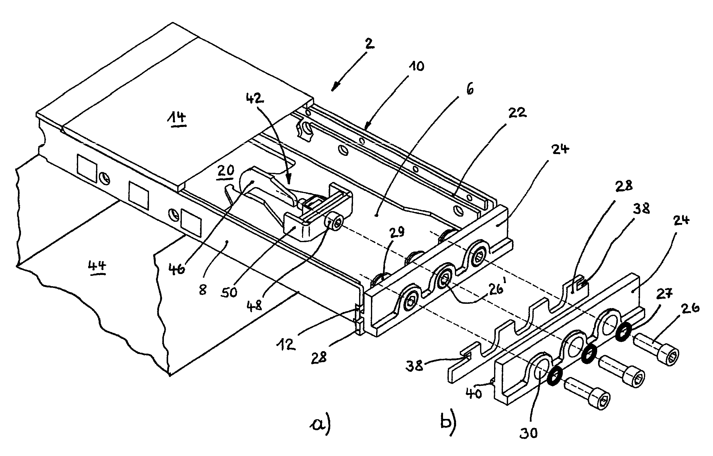
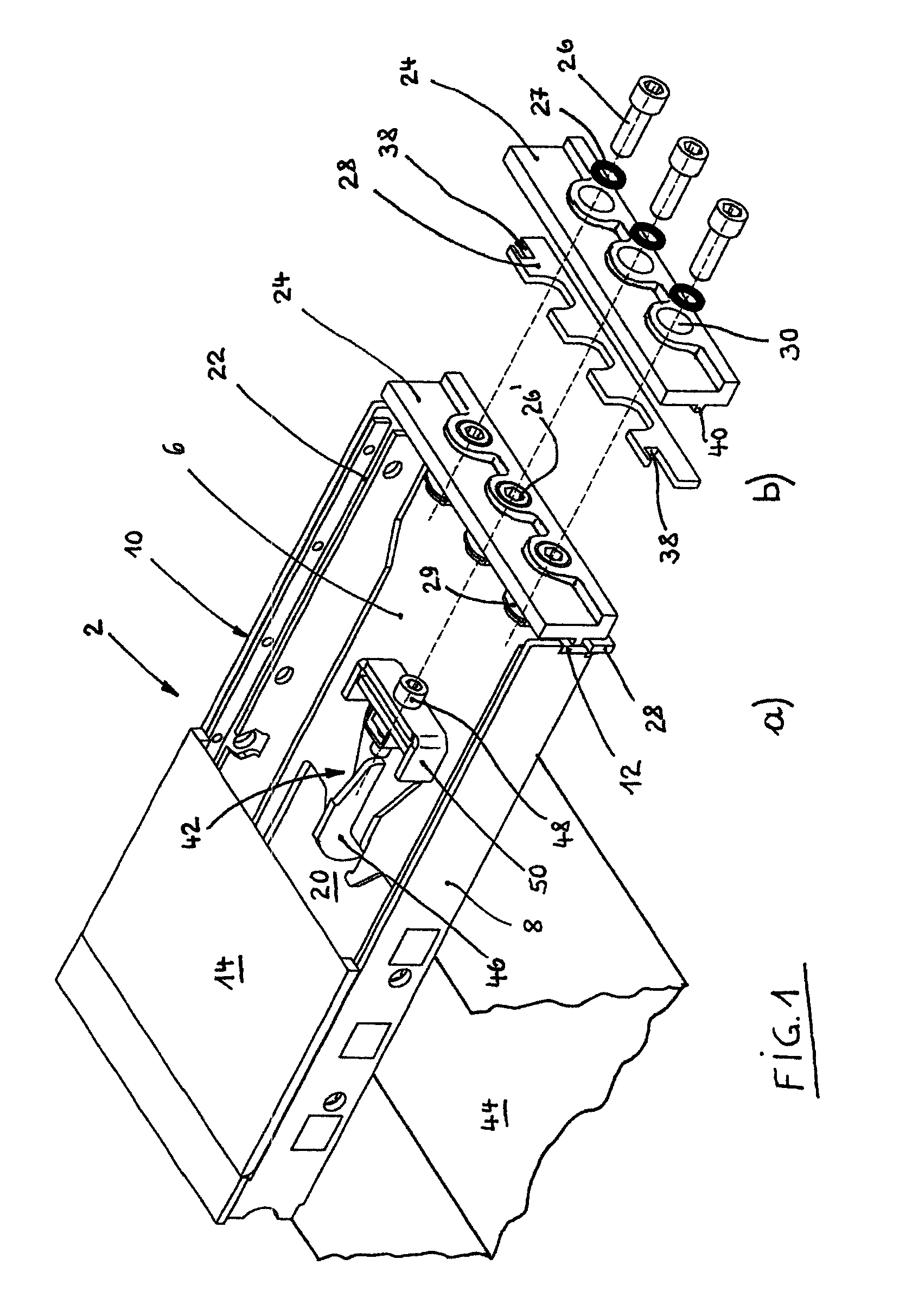
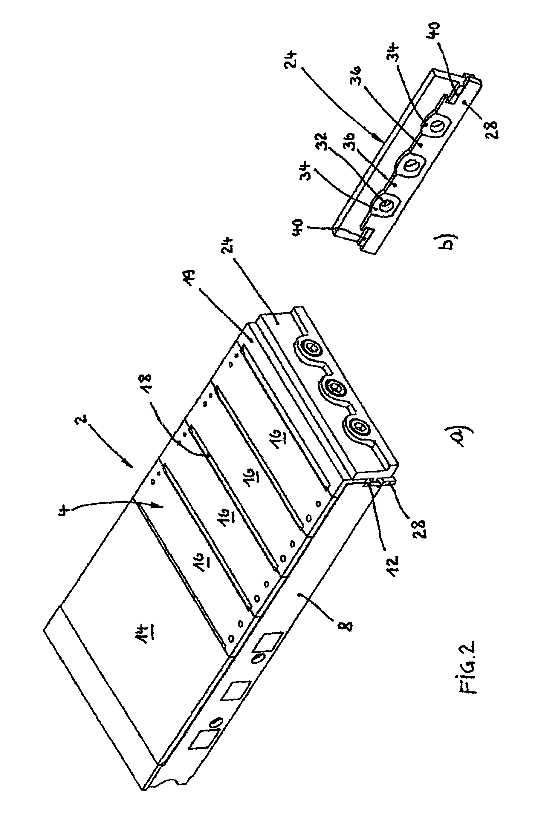
[0029]The grate plate 2 illustrated in FIGS. 1a and 2a is designed approximately in the shape of a box, with a top wall 4, a bottom wall 6, two side walls 8, 10, a rear wall not visible in the figures and a front wall 12.

[0030]As particularly shown in FIG. 2, the top wall 4 consists essentially of a closed initial blade 14, which corresponds approximately to the area of the overlap with the preceding grate plate (not shown), a plurality of middle blades 16, between each of which a blower slot 18 is left open, and an angular final blade 19, which forms the closure of the top wall 4 and the upper area of the front wall 12.

[0031]The bottom wall 6 has in its rear area, with which it rests on a grate carrier 44, an opening 20, by means of which cooling air is introduced into the grate plate, for example. This cooling air flows through the blower slots 18 into the bulk material lying on the grate plate.

[0032]The side walls 8, 10 have on each of their inner sides a guide slot 22, into whic...


PUM


Abstract

A grate plate arrangement for stepped reciprocating grates includes a grate plate with a front plate fastened to a front wall in the direction of conveyance. The grate plate includes an adjustment plate being clamped between the front plate and the front wall of the grate plate for adjusting a motion gap between the front end of the grate plate and the following grate plate in the direction of conveyance which forms the next grate step. The adjustment plate is calibrated with the front plate still only loosely assembled, in its vertical position that forms the motion gap, and is held in this position by clamping the front plate.

Description

CROSS-REFERENCE TO RELATED APPLICATION[0001]This application claims the priority benefit of German Patent Application No. 10 2009 009 285.4 filed on Feb. 17, 2009, the entirety of which is fully incorporated herein by reference.STATEMENT CONCERNING FEDERALLY SPONSORED RESEARCH OR DEVELOPMENT[0002]Not Applicable.FIELD OF THE INVENTION[0003]The present invention relates to a grate plate arrangement for stepped reciprocating grates including a box-like grate plate with a front plate fastened to the front wall in conveying direction, and means for adjusting a motion gap between the front end of the grate plate and the following grate plate in conveying direction.BACKGROUND OF THE INVENTION[0004]Stepped reciprocating grates are used for the continuous conveyance and simultaneous cooling or other types of treatment of bulk materials that are deposited on the grate and to which cooling air or another treatment gas is fed from below through blower openings in the grate surface.[0005]A plura...

Claims


Application Information

Patent Timeline
Patent Type & Authority Patents(United States)
IPC IPC(8): F23H7/08B65G25/04
CPCF27D15/022
Inventor VAN DIEPEN, NICOLAASSCHNEIDER, RICHARDWINDMOLLER, SANDO KLAAS
Owner IKN GMBH
Why Eureka
Try Eureka