Charging station for cordless ultrasound cart

a charging station and ultrasound cart technology, applied in the direction of electrical apparatus casings/cabinets/drawers, coupling device connections, instruments, etc., can solve the problems of affecting the use of ultrasound carts, containing cords, and general nuisance, and achieve the effect of facilitating their us

Active Publication Date: 2013-03-19
FUJIFILM SONOSITE
View PDF85 Cites 58 Cited by
  • Summary
  • Abstract
  • Description
  • Claims
  • Application Information

AI Technical Summary

Benefits of technology

[0007]The present invention is directed to systems and methods which establish physically fixed or semi-fixed charger stations that work in conjunction with a mobile cart, such as an ultrasound cart. The cart may comprise a power supply, such as a large battery, with the capacity to keep one or more devices of the system thereof operating, suc

Problems solved by technology

Several problems exist when the cart is moved to a patient's bedside.
Some of these problems revolve around the fact that often there is a myriad of equipment plugged into the wall outlets in a patient's room and available outlets are scarce.
Even when outlets are available, they typically are a large distance from where the cart is to be used thereby necessitating a long power cord attached to the cart.
In addition to the problem of simply running this cord from the cart to the wall outlet, there is the problem of containing the cord when the cart is being moved from location to location.
In general, power cords on devices, particularly long power cords used in cramped conditions, are a general nuisance and worse, often unsafe.
In the medical setting discussed above, when the carts are not in actual use with a patien

Method used


Image

  • Charging station for cordless ultrasound cart
  • Charging station for cordless ultrasound cart
  • Charging station for cordless ultrasound cart

Examples


Embodiment Construction

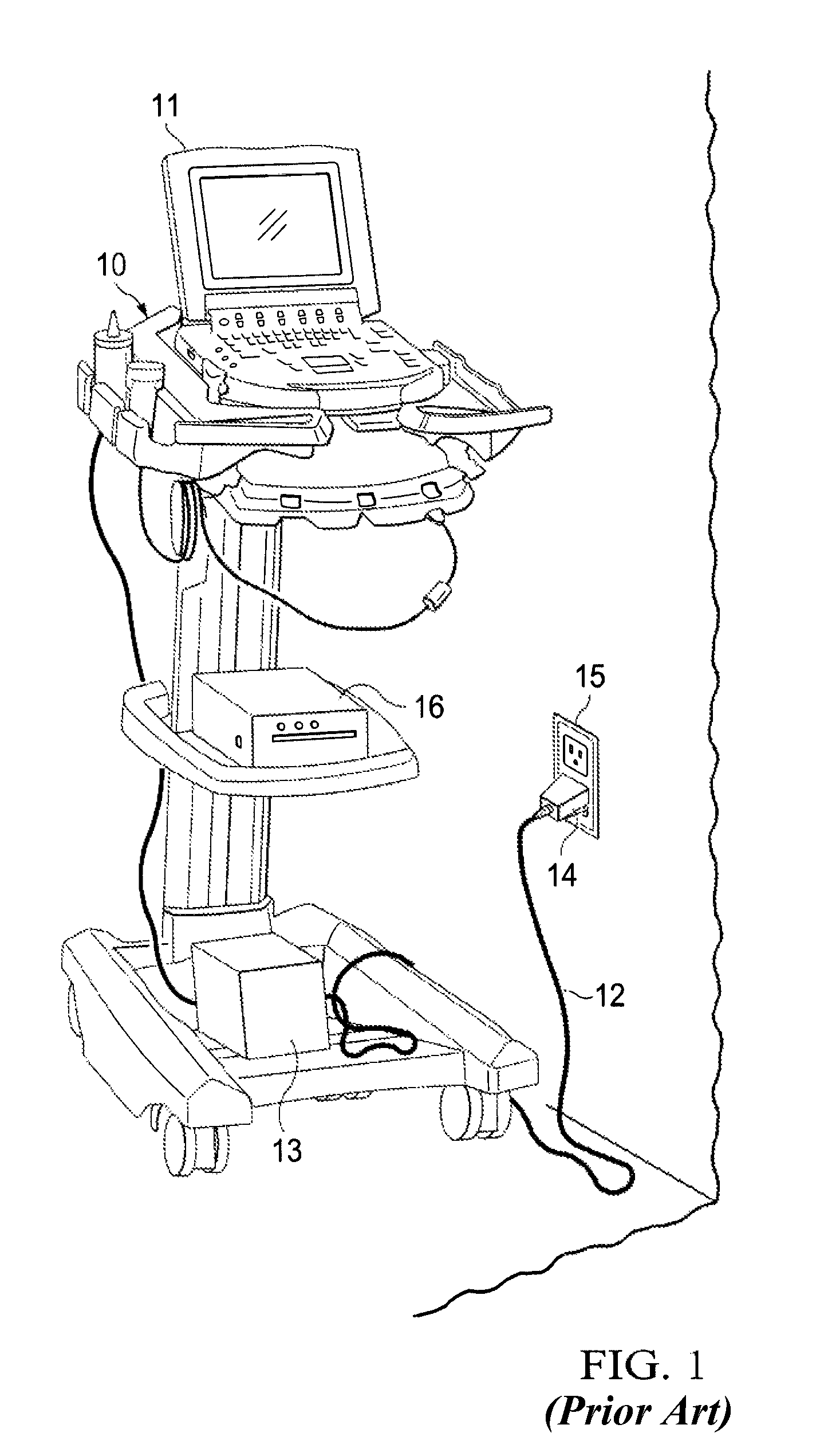
[0025]FIG. 1 shows a typical prior art medical cart 10 of the type used for sonography equipment, such as device 11. The ultrasound system could have an internal battery (not shown). Note that in this case the ultrasound cart does not have a battery but it does have power outlet 13 connected to long cord 12. The cord has plug end 14 which is adapted to plug into a wall outlet, such as wall outlet 15 to provide power to the system. Auxiliary equipment 16 is plugged into outlet box 13. This could be, for example, a printer, a video recorder, a VCR or any other type of equipment, all of which receive power from the cart, via the premises power outlet. As discussed above, when the power plug is removed from the wall outlet none of the auxiliary equipment can operate unless it has internal battery power.

[0026]In operation, when it is desired to move the cart to a patient location the cord is unplugged and wrapped around the cart, or onto a reel, or most often, held in the hand of the car...


PUM


Abstract

The present invention is directed to a system and method which establishes physically fixed charger stations that work in conjunction with a medical cart, such as an ultrasound cart. The medial cart contains a power supply, such as a large battery, with the capacity to keep the system going for a full day's use. Each docking station provides a fixed location for one or more carts and allows each cart to plug directly into a source of premises power. The docking stations allow the plugged-in cart to recharge while the cart is not in use. In one embodiment, a large Class C battery capable of powering not only the medical device but its associated peripherals as well. Thus, when the cart is removed from the docking station and taken to a patient's location, the equipment on the cart can be operated without the need for plugging the cart into a wall outlet thereby eliminating the need for a long power cord. The fixed locations of the docking station also eliminates the need for hunting “misplaced” carts.

Description

CROSS-REFERENCE TO RELATED APPLICATIONS[0001]The present application is a continuation-in-part of co-pending, commonly assigned U.S. patent application Ser. No. 12 / 392,869 entitled “CHARGING STATION FOR CORDLESS ULTRASOUND CART,” filed Feb. 25, 2009, and this application is related to U.S. patent application Ser. No. 11 / 590,010 filed Oct. 31, 2006, entitled “DOCKING STATION HAVING AUXILIARY POWER MANAGEMENT FOR USE WITH PORTABLE MEDICAL EQUIPMENT,” the disclosures of which are hereby incorporated herein by reference.TECHNICAL FIELD[0002]This disclosure relates to battery charging systems and more particularly to systems and methods for maintaining the batteries within a portable medical device cart charger.BACKGROUND OF THE INVENTION[0003]It is now common practice in a variety of situations to use portable medical devices, such as ultrasound devices, for examination of patients at the location of the patient. Often this location is the patient's bed in a hospital room. The portable ...

Claims


Application Information

Patent Timeline
IPC IPC(8): H01R33/00
CPCA61B8/4433A61B8/4405
Inventor HANSEN, JOSHUA M.DAVIDSON, DANIELFINE, RICHARD A.
Owner FUJIFILM SONOSITE
Why Eureka
Try Eureka