Light-emitting device and lighting apparatus incorporating same

a technology of light-emitting devices and lighting apparatuses, which is applied in the direction of lighting and heating apparatus, semiconductor devices for light sources, discharge tubes luminescnet screens, etc., can solve the problems of difficult design of resin detailed shape, unsuitable for diffused light in all directions, and disclosed structure of reflective frames, etc., to achieve wide directivity and extract light over a wide area

Active Publication Date: 2013-03-19
USHIO DENKI KK
View PDF27 Cites 144 Cited by
  • Summary
  • Abstract
  • Description
  • Claims
  • Application Information

AI Technical Summary

Benefits of technology

[0008]To overcome the foregoing advantage, it is an object of the present invention to provide a light-emitting device suitable as an alternative to a linear light source that is placed in the air like a filament and a lighting apparatus incorporating such a light-emitting device. It is another object of the invention to provide a light-emitting device that decreases light directivity and that easily extracts light in all directions.
[0010]With the light-emitting device of the first aspect of the invention, since, as described above, the first and second resins are formed of optically transparent resin, it is possible to make both the resins function as light guiding members. Thus, it is possible to guide light toward the back side of the lead on which light-emitting diodes are arranged. Since the bar-shaped package is used, linear light can be generated. Moreover, since outer lead portions used for external connection protrude sideways from both left and right ends of the package, it is possible to increase workability when adjacent ones of the light-emitting device are firmly attached such as by welding.
[0011]In the light-emitting device of the first aspect of the invention, the second resin may include fluorescent material. Thus, it is possible to change the color of light emitted from the light-emitting device with the fluorescent material included in the second resin.
[0013]Since, in the lighting apparatus of the second aspect of the invention, as described above, adjacent ones of the outer lead portions are firmly attached and connected in series such that adjacent ones of the bar-shaped light-emitting devices are V-shaped, the lighting apparatus can take the same form of light emission as a metal filament. Moreover, since the bar-shaped light-emitting devices are formed of optically transparent resin, it is possible to provide a lighting apparatus that can extract light not only in directions toward the front and back of the leads but also in directions in which the outer lead portions used for external connection extend and that evenly emits light 360 degrees, that is, in all directions.
[0014]As described above, according to the present invention, it is possible to provide light-emitting devices that can extract light over a wide area and that have wide directivity and a lighting apparatus incorporating such light-emitting devices. It is also possible to provide light-emitting devices in which adjacent ones of the light-emitting devices are firmly attached with ease.

Problems solved by technology

The structure of the reflective frame disclosed in JP-A-2003-168824 is not suitable to diffuse light in all directions.
In the structure disclosed in JP-T-2003-519929 and having no reflective frame, since a sealing resin is molded at one time, it is difficult to design the detailed shape of the resin.
In particular, when a fluorescent material or a light diffusing material is contained in the resin, it is difficult to place the contained material in an optimum position due to the relationship between the specific gravities of the resin and the contained material.
Thus, they are not suitable as an alternative to a linear light source placed in the air like a metal filament.

Method used


Image

  • Light-emitting device and lighting apparatus incorporating same
  • Light-emitting device and lighting apparatus incorporating same
  • Light-emitting device and lighting apparatus incorporating same

Examples


Embodiment Construction

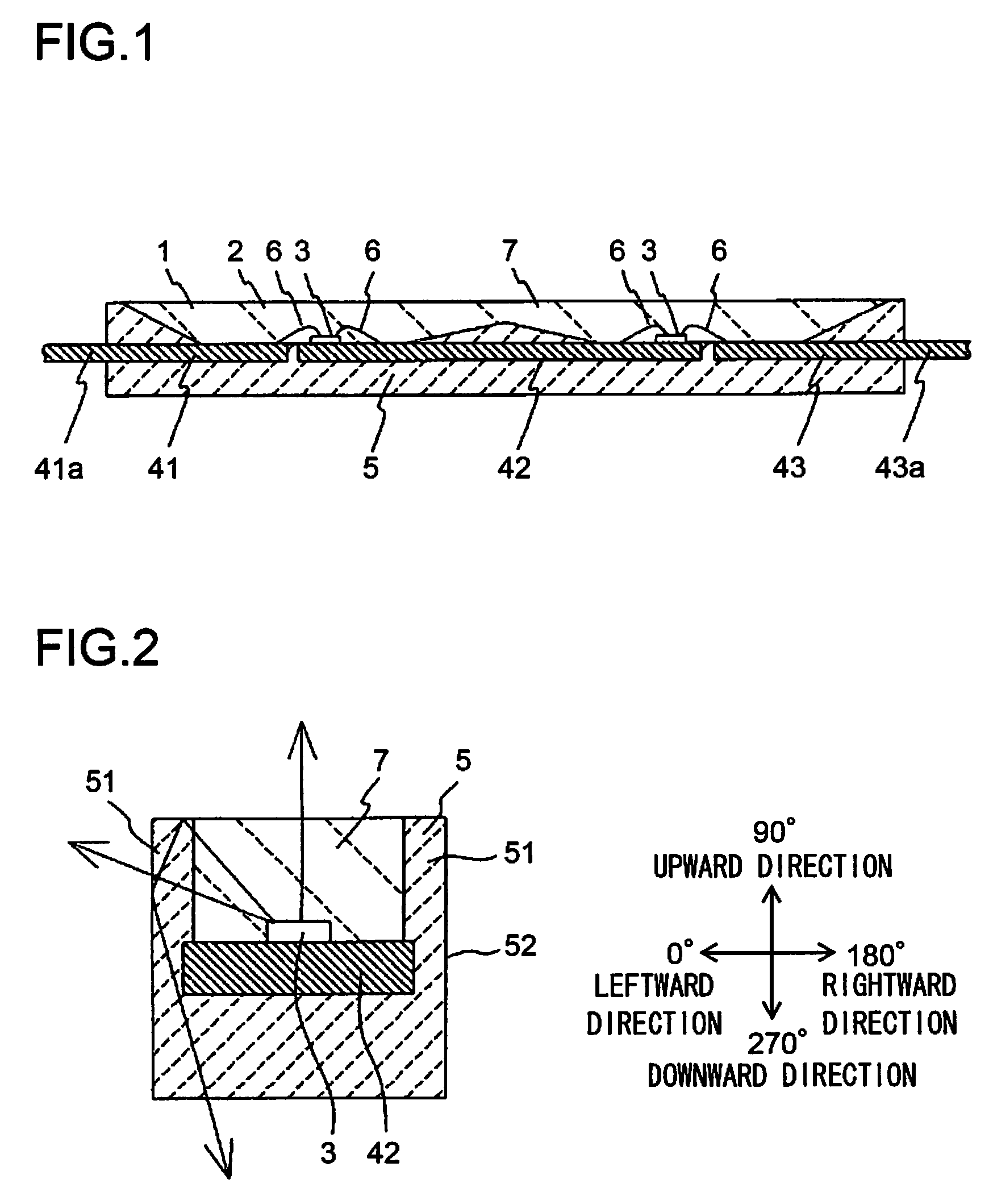
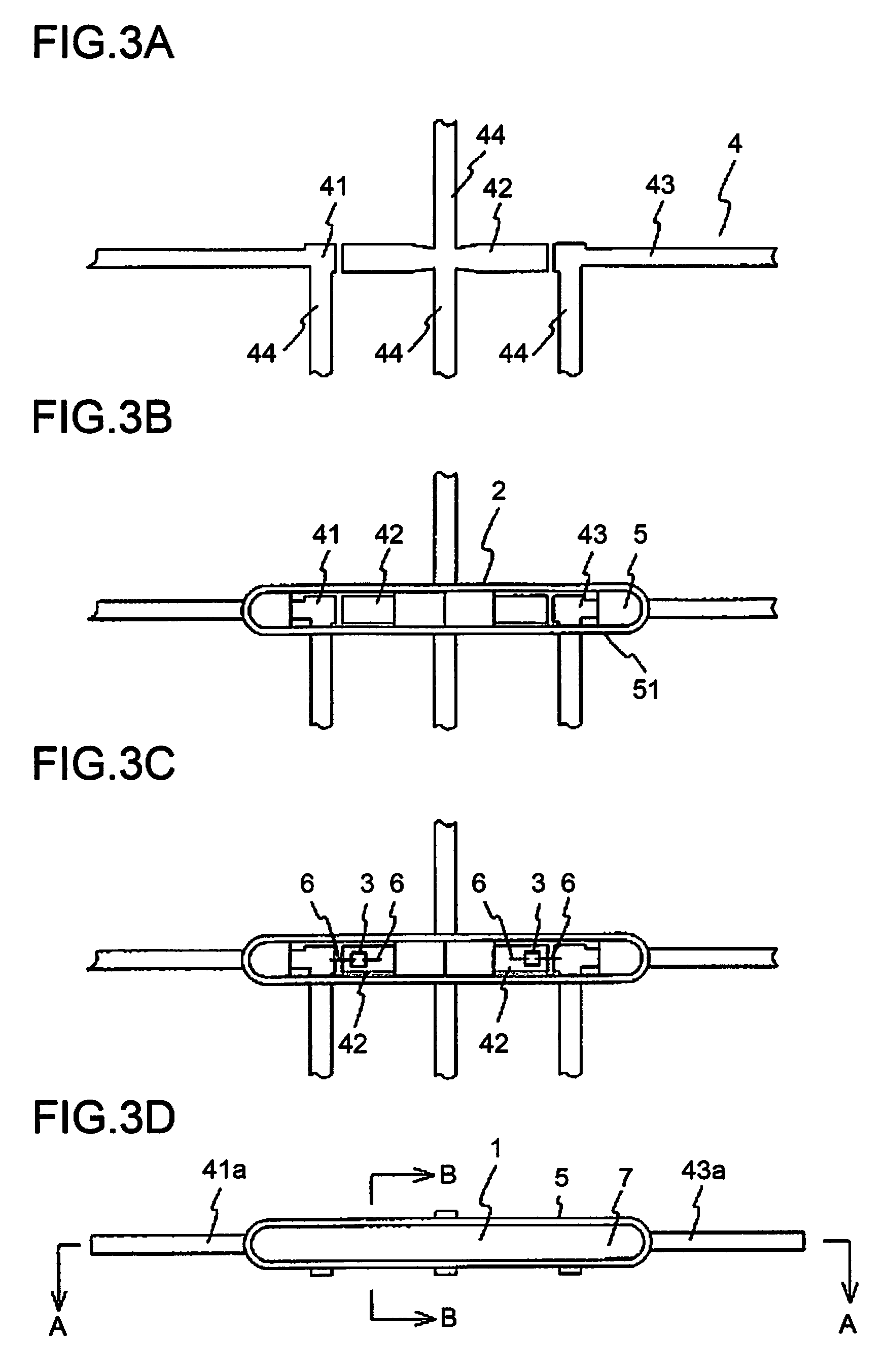
[0026]Embodiments of the present invention will be described below with reference to the accompanying drawings. FIG. 1 is a cross-sectional view taken along a lengthwise direction of a light-emitting device according to an embodiment of the invention. FIG. 2 is a cross-sectional view taken along a widthwise direction of the light-emitting device according to the embodiment of the invention. FIG. 1 shows the cross-sectional view taken along line A-A of FIG. 3D; FIG. 2 shows a cross-sectional view taken along line B-B of FIG. 3D.

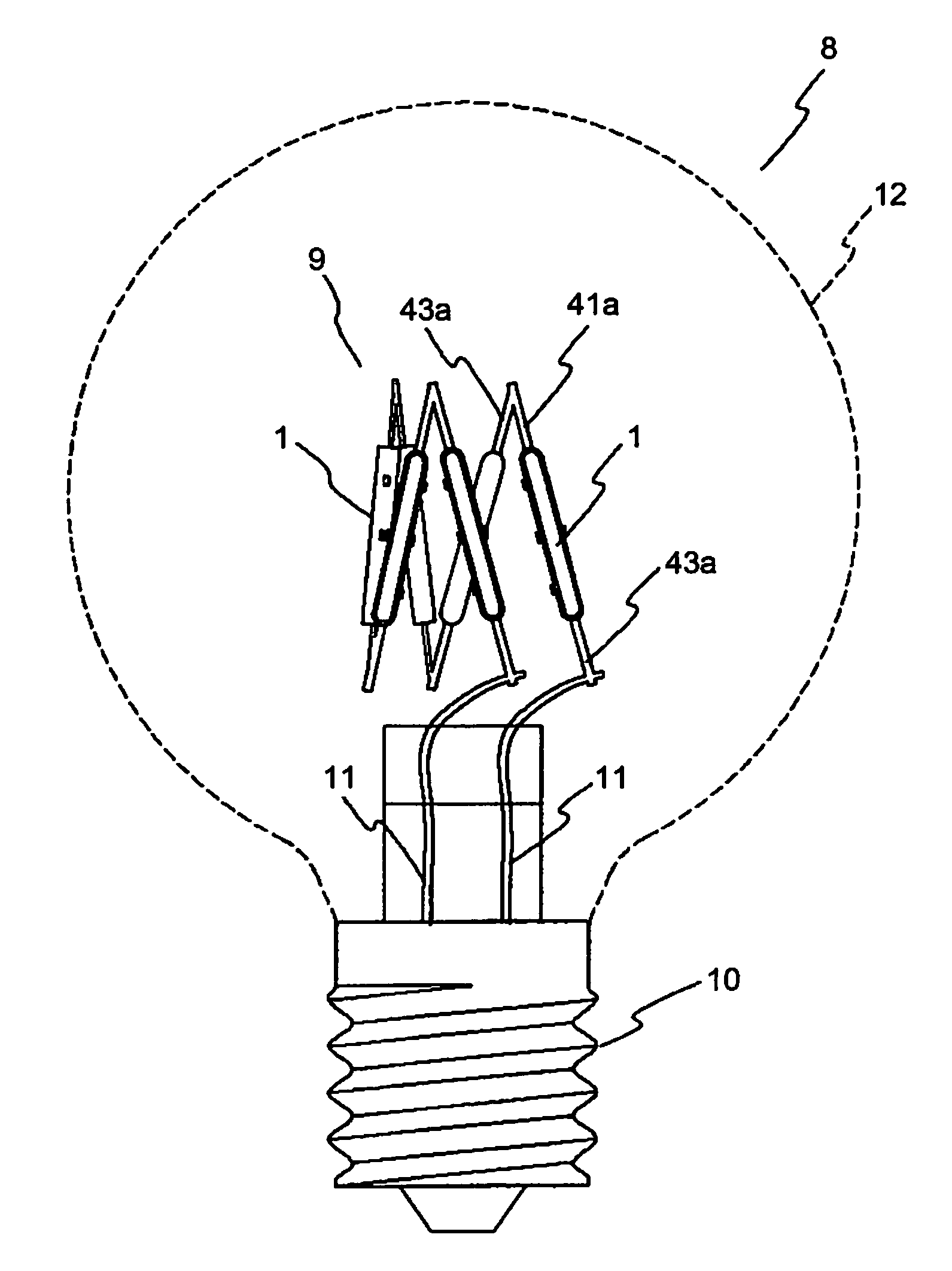
[0027]A light-emitting device 1 is configured such that light-emitting elements 3 are incorporated in a lead-frame type package 2, that these light-emitting elements 3 are sealed with resin and that the light-emitting device 1 is formed overall in the shape of an elongated bar. The package 2 is formed in the shape of an elongated bar extending sideways such that parts of a plurality of leads 41, 42 and 43 formed with a lead frame 4 are exposed and that the lea...


PUM


Abstract

A light-emitting device is provided that can extract light in all directions and that has wide directivity. This light-emitting device includes: an elongated bar-shaped package extending sideways, the package being formed such that a plurality of leads are formed integrally with a first resin with part of the leads exposed; a light-emitting element that is fixed onto at least one of the leads and that is electrically connected to at least one of the leads; and a second resin sealing the light-emitting element. In the light-emitting device, the first resin and the second resin are formed of optically transparent resin, and the leads have outer lead portions used for external connection and protruding sideways from both left and right ends of the package.

Description

[0001]This application is based on Japanese Patent Application No. 2008-008899 filed on Jan. 18, 2008, the contents of which are hereby incorporated by reference.BACKGROUND OF THE INVENTION[0002]1. Field of the Invention[0003]The present invention relates to a light-emitting device and a lighting apparatus incorporating such a light-emitting device, and more particularly to a light-emitting device provided with a light-emitting element and a lighting apparatus incorporating such a light-emitting device.[0004]2. Description of Related Art[0005]In JP-A-2003-168824, there is disclosed a structure in which a light-emitting element and a resin for sealing the light-emitting element are provided in the reflective frame of a package. A lead frame is employed as the package, and the reflective frame is formed of white resin. Since the structure includes the reflective frame as described above, light emitted from the light-emitting element is extracted with increased directivity in one direc...

Claims


Application Information

Patent Timeline
Patent Type & Authority Patents(United States)
IPC IPC(8): H01J5/16H01J61/40H01K1/26H01K1/30H01L33/48H01L33/50H01L33/54H01L33/56H01L33/62
CPCF21K9/135H01L33/52H01L25/0753H01L2224/48247H01L33/56H01L2224/48091F21Y2111/001H01L33/54H01L2924/3025F21Y2101/02H01L2924/00014H01L2924/00F21K9/232F21Y2115/10F21Y2107/00
Inventor HAKATA, KUNIHIKOMATSUOKA, TOMOMI
Owner USHIO DENKI KK
Why Eureka
Try Eureka