Charge status display apparatus and electric power supply control apparatus

a technology of charging status and display apparatus, which is applied in the direction of secondary cell servicing/maintenance, instruments, wireless architecture usage, etc., and can solve problems such as reducing the possibility

Inactive Publication Date: 2013-03-19
DENSO CORP
View PDF9 Cites 37 Cited by
  • Summary
  • Abstract
  • Description
  • Claims
  • Application Information

AI Technical Summary

Benefits of technology

[0010]The present invention takes the above problem into consideration. It is an object of the present invention to reduce a possibility that a user mistakenly manipulates a wrong manipulation device in an electric power supply system, thereby starting an electric power supply control or a charge status display with respect to an unintended vehicle battery. Herein, the electric power supply system is provided with several manipulation devices, which are arranged in positions distant from several charge terminals.
[0013]Thus, even if an intended vehicle is connected to any of the charge terminals, when the first manipulation section undergoes the first manipulation, the charge status of the intended vehicle associated with the first manipulation section can be displayed. Further, if at least the user remembers that the intended vehicle is associated with the first manipulation section, the user can certainly confirm the charge status of the intended vehicle without needing to be conscious of which charge terminal the intended vehicle is connected with. That is, such a configuration can decrease a possibility that a user mistakenly executes a manipulation to a wrong manipulation section to thereby display a charge status of a battery of an unintended vehicle.
[0016]Thus, even if an intended vehicle is connected to any of the charge terminals, as long as at least the user keeps in remembrance the association of the vehicle with the first manipulation section, without need of concerning a charge terminal the vehicle is connected with, the start and stop of the charge of a battery of the vehicle are certainly controllable. That is, such a configuration can decrease a possibility that a user mistakenly executes a manipulation to a wrong manipulation section to thereby display a charge status of a battery of an unintended vehicle.

Problems solved by technology

That is, such a configuration can decrease a possibility that a user mistakenly executes a manipulation to a wrong manipulation section to thereby display a charge status of a battery of an unintended vehicle.

Method used


Image

  • Charge status display apparatus and electric power supply control apparatus
  • Charge status display apparatus and electric power supply control apparatus
  • Charge status display apparatus and electric power supply control apparatus

Examples


first embodiment

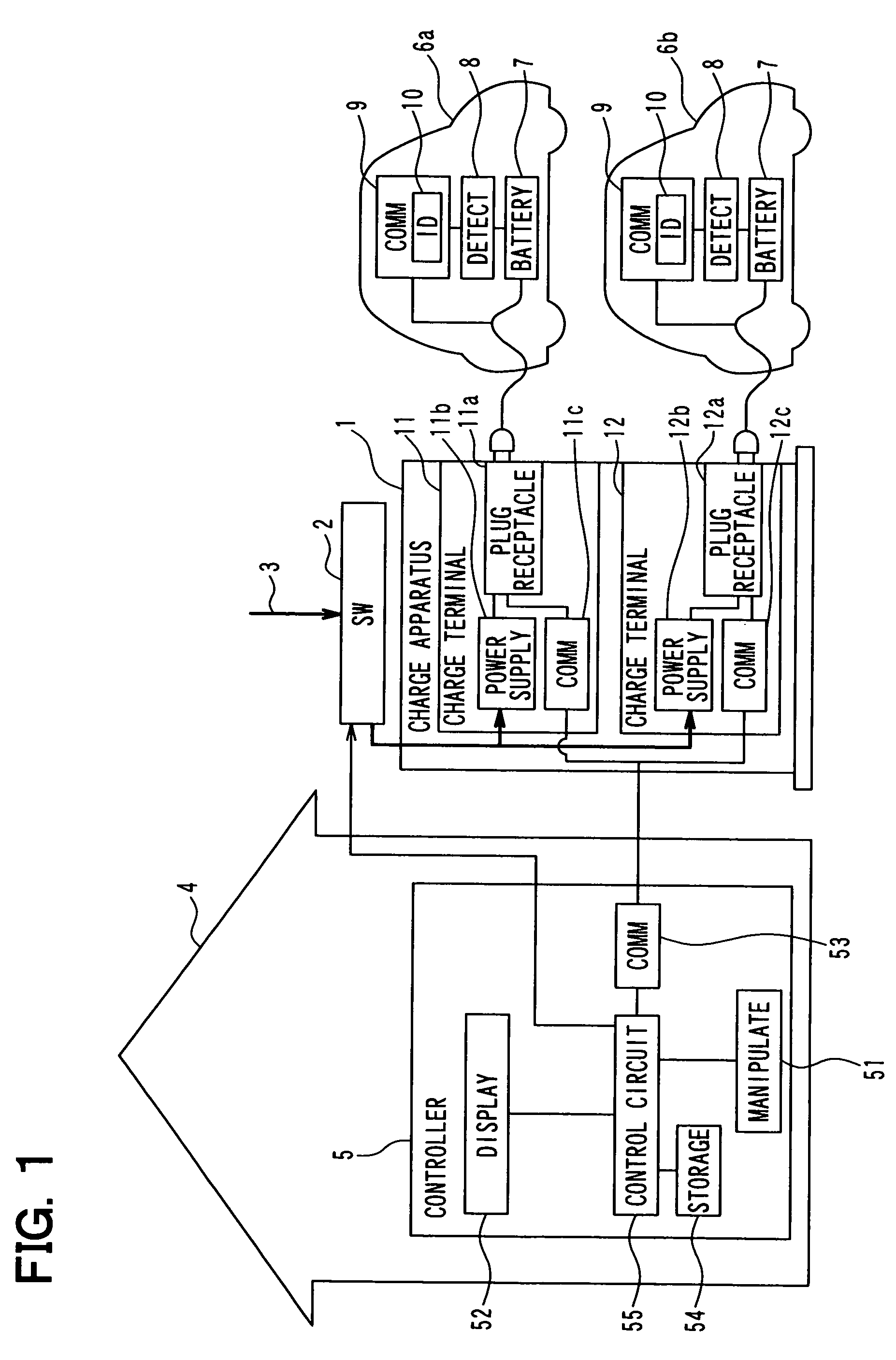
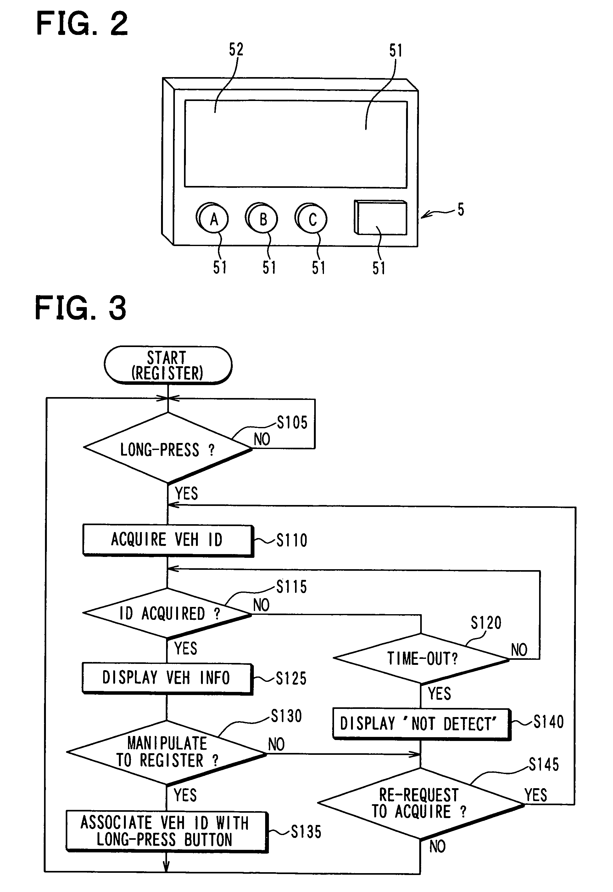
[0037]The following describes a first embodiment of the present invention. As illustrated in FIG. 1, an electric power supply system for home use according to the present first embodiment includes the following: a charge apparatus 1 (also referred to as a charger), a switch device 2, a controller 5 (also serving as an example of a charge status display apparatus) in a building 4 such as a house, and plug-in charge vehicles 6a, 6b, each of which is connected with the charge apparatus 1 and then receives charge (i.e., electric power supply).

[0038]Each subject vehicle, i.e., each of the vehicles 6a, 6b, includes a battery 7 serving as a rechargeable battery (i.e., secondary battery) which is able to be repeatedly charged, i.e., which can receive the charge repeatedly; a detection device 8 which detects a charge status of the battery 7; and a communications device 9 to communicate with the charge apparatus 1 as a connection destination. The charge status of the battery 7 is represented ...

second embodiment

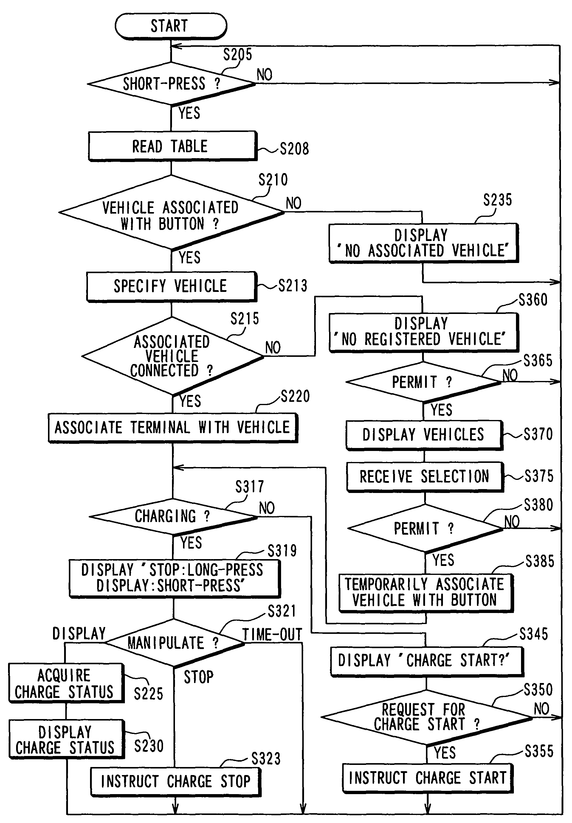
[0101]The following explains a second embodiment. The present second embodiment differs from the first embodiment in that the control circuit 55 of the controller 5 (serving as an example of a charge status display apparatus and an example of an electric power supply control apparatus) of the present embodiment executes a power supply control and charge status display process in FIG. 10 instead of the charge status display process illustrated in FIG. 7. It is noted that the sections or steps designated by the same reference numerals in FIGS. 7 and 10 are identical to each other, therefore eliminating a detailed explanation.

[0102]Hereinafter, the operation of the electric power supply system at the time of the control circuit 55 executing this electric power supply control and charge status display processing is explained. The control circuit 55 executes a predetermined program in the ROM, thereby realizing the electric power supply control and charge status display process. In addit...


PUM

PropertyMeasurementUnit
timeaaaaaaaaaa
electric poweraaaaaaaaaa
charge statusaaaaaaaaaa

Abstract

When a user performs a short-press manipulation to A button or B button, a vehicle ID associated with either A button or B button having received the short-press manipulation is specified based on a button-vehicle correspondence table. Charge status information of a battery of a vehicle corresponding to the above associated vehicle ID is acquired from the vehicle. Thereby, the display device displays the acquired charge status information or the electric power supply is started to the battery of the vehicle corresponding to the vehicle ID.

Description

CROSS REFERENCE TO RELATED APPLICATION[0001]The present application is based on and incorporates herein by reference Japanese Patent Application No. 2009-206996 filed on Sep. 8, 2009.FIELD OF THE INVENTION[0002]The present invention relates to a charge status display apparatus and an electric power supply control apparatus.BACKGROUND OF THE INVENTION[0003][Patent document 1] JP-2008-199752 A (EP-2,110,923 A1)[0004]There is known a technology of an electric power supply system in which several charge terminals are arranged in a parking lot such that a vehicle is connected with each charge terminal. Further, each charge terminal supplies a battery of the connected vehicle with an electric power from a commercial power source.[0005]For example, in a technology described in Patent document 1, when a manipulation device (panel) of one charge terminal (charge manipulation device) is manipulated, the power supply begins from the charge terminal to the battery of the vehicle.[0006]Such a ma...

Claims


Application Information

Patent Timeline
Patent Type & Authority Patents(United States)
IPC IPC(8): H01M10/46B60L50/15
CPCB60L11/1816B60L11/1846H01M10/44H04Q9/00G01R31/3689Y02T10/7005H04Q2209/30Y02T90/169Y02T90/121Y02T90/14Y02T90/128Y04S30/14H04Q2209/43Y02T90/163B60L2240/70B60L2250/12Y02T90/16G01R31/371B60L53/14B60L53/65B60L58/12B60L53/305Y02T10/70Y02T10/7072Y02T10/72Y02T90/12Y02T90/167Y02E60/10
Inventor TAGUCHI, SHINYAASADA, HIROSHIGEKANAMORI, TAKASHI
Owner DENSO CORP
Why Eureka
Try Eureka