Rotational position sensor having axially central sensor unit

a sensor unit and rotational position technology, applied in the direction of magnetic measurements, instruments, measurement apparatus components, etc., can solve the problems of upsizing the structure, the inability to detect the rotational position of the rotor or the shaft with high accuracy, etc., to achieve the effect of reducing the size of the structur

Inactive Publication Date: 2013-03-19
MIKUNI CORP
View PDF13 Cites 1 Cited by
  • Summary
  • Abstract
  • Description
  • Claims
  • Application Information

AI Technical Summary

Benefits of technology

[0009]To address the above issues, it is one aspect to provide a rotational position sensor capable of detecting a rotational angle position of a rotating body with high accuracy by supporting the rotating body such as a rotor and a shaft of which rotational position is detected so as to obtain an automatic alignment effect even with occurrence of aging variation such as wearing at a bearing area. In addition, with the rotational position sensor, structural simplification, miniaturization and the like can be achieved by effectively utilizing an area on an axis line (i.e., a rotational center line) of the rotating body as a location for component arrangement.

Problems solved by technology

As a result, there is a fear that the relative positional relation between the movable contact point and the fixed terminal or the relative positional relation between the movable magnet and the Hall element is varied and that the rotational position of the rotor or the shaft cannot be detected with high accuracy.
Accordingly, there has been a problem that an area around the shaft portion cannot be effectively utilized as the arrangement area of the components, which causes an upsizing of the structure.

Method used


Image

  • Rotational position sensor having axially central sensor unit
  • Rotational position sensor having axially central sensor unit
  • Rotational position sensor having axially central sensor unit

Examples


Embodiment Construction

[0046]Reference will now be made in detail to embodiments, examples of which are illustrated in the accompanying drawings, wherein like reference numerals refer to like elements throughout.

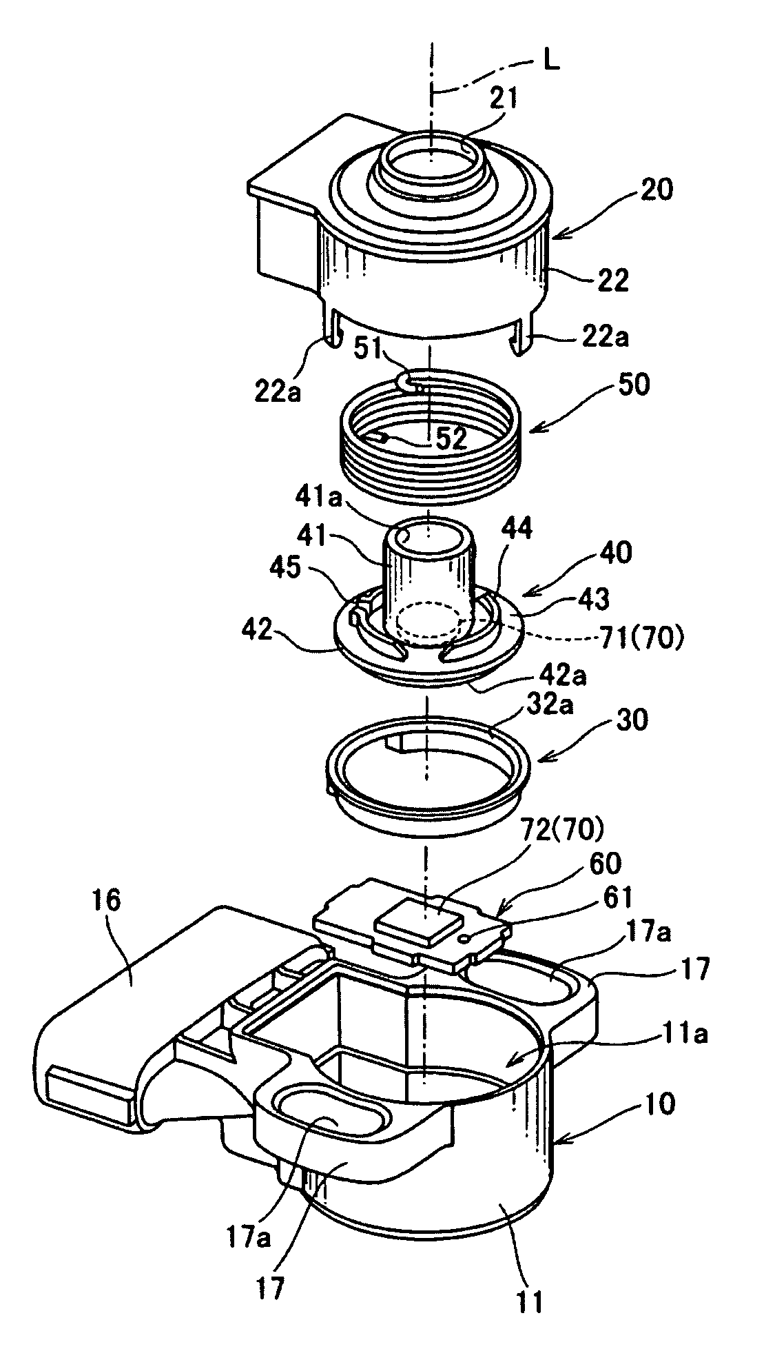
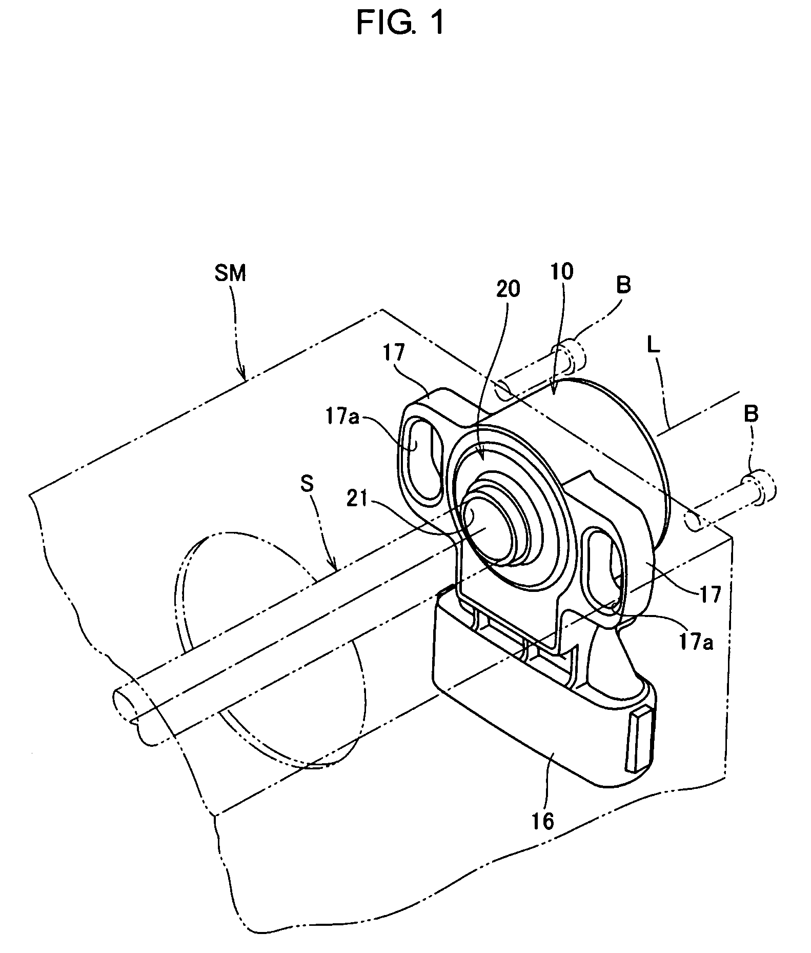
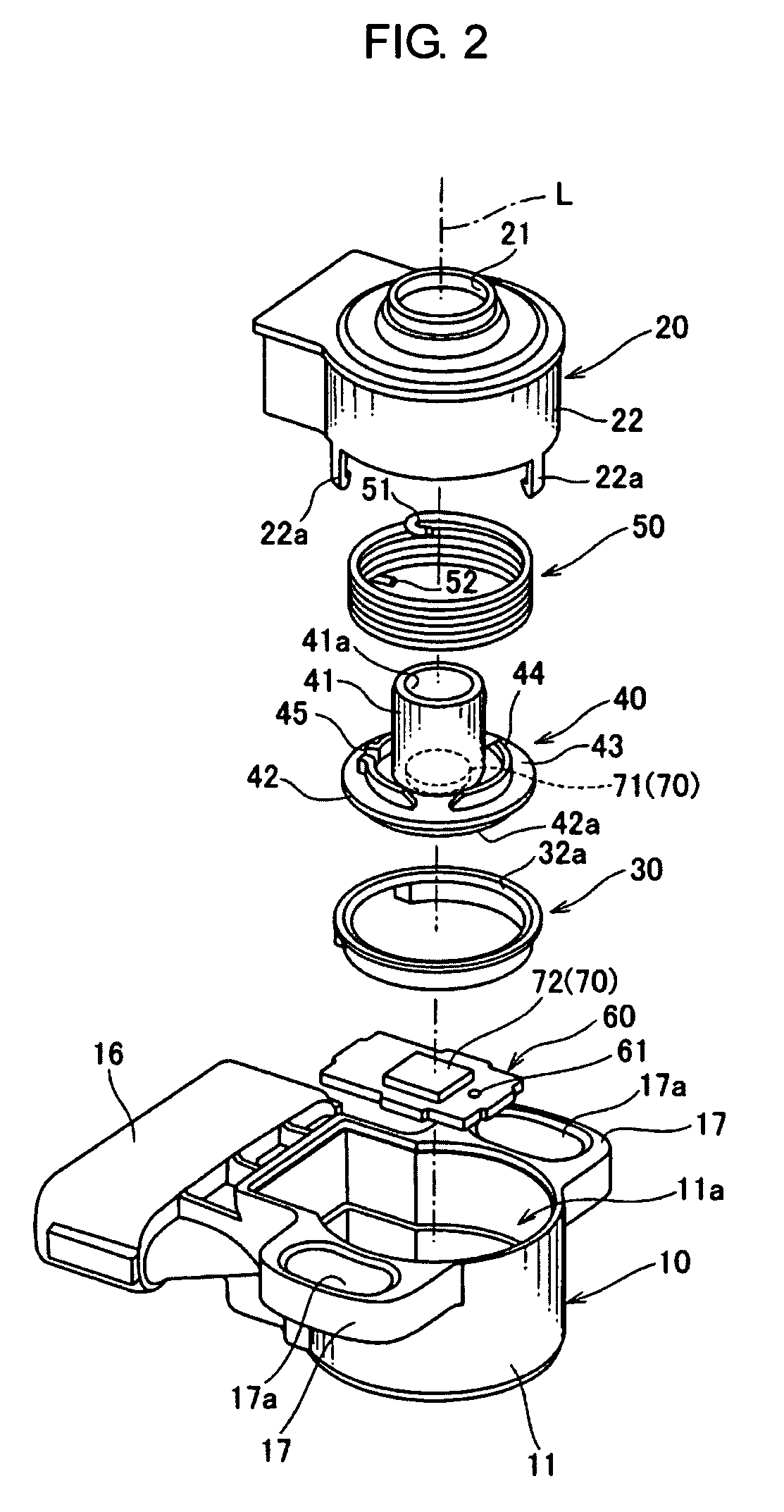
[0047]FIGS. 1-5, 6A, 6B, 7 and 8 are views illustrating an embodiment of a rotational position sensor. FIG. 1 is a perspective view illustrating an application example of the rotational position sensor. FIGS. 2 and 3 are exploded perspective views of the rotational position sensor. FIG. 4 is a sectional view of the rotational position sensor. FIG. 5 is a partially sectioned view of the rotational position sensor. FIG. 6A is a plane view and FIG. 6B is a side view, both illustrating a housing main body which constitutes a part of the rotational position sensor. FIG. 7 is a sectional view illustrating a rotating body and a guide member included in the rotational position sensor. FIG. 8 is a schematic view illustrating a sensor unit included in the rotational position sensor.

[0048]For example, the ro...


PUM


Abstract

A rotational position sensor includes a rotating body rotatably supported around a predetermined axis line by a bearing portion of a housing and a sensor unit having a movable sensor element arranged at the rotating body to detect a rotational angle position of the rotating body and a fixed sensor element arranged at the housing. The rotating body includes a tapered annular contact face defining a part of a virtual cone face with a vertex on the axis line and the bearing portion includes a tapered annular bearing face rotatably supporting the annular contact face on the virtual cone face. Accordingly, the rotating body is consistently located on the axis line due to an automatic alignment effect. Therefore, the rotational angle position of the rotating body can be detected with high accuracy even with occurrence of aging variation such as wearing at a bearing area.

Description

CROSS-REFERENCE TO RELATED APPLICATIONS[0001]This application is a continuation, filed under 35 U.S.C. §111(a), of PCT international application No. PCT / JP2009 / 052188, filed Feb. 10, 2009, which application claims the priority benefit of Japanese patent application No. 2008-089905, filed Mar. 31, 2008, the disclosures of which are incorporated herein by reference.BACKGROUND[0002]1. Field[0003]Embodiments relate to a rotational position sensor which detects an angle position of a rotating body, and in particular, relates to a contact-type or non-contact type rotational position sensor which detects a rotational angle of a throttle shaft for an engine mounted on a vehicle and the like, a depression angle of an accelerator pedal which is swung around a predetermined axis, and the like.[0004]2. Description of the Related Art[0005]A rotational position sensor known in the related art includes a housing having a bearing hole in the radial direction and a bearing end face in the thrust dir...

Claims


Application Information

Patent Timeline
Patent Type & Authority Patents(United States)
IPC IPC(8): G01B7/30G01B7/14
CPCG01D5/145G01D11/245G01D5/24442G01D2205/60
Inventor SOYAMA, HIROAKIKOMOTO, YOSHINOBU
Owner MIKUNI CORP
Why Eureka
Try Eureka