High efficiency micro projection optical engine

a micro-projection, optical engine technology, applied in projectors, color television details, instruments, etc., can solve the problems of low efficiency, low efficiency, and small size of liquid crystal projection, and achieve simple and compact structure, enhanced efficiency of optical engine, and high light utilization ratio

Inactive Publication Date: 2013-03-26
BUTTERFLY TECH SHENZHEN
View PDF13 Cites 4 Cited by
  • Summary
  • Abstract
  • Description
  • Claims
  • Application Information

AI Technical Summary

Benefits of technology

[0005]For this reason, it is necessary to provide a high efficiency micro projection optical engine with compact and simple configuration, whose light path is shorter and size is smaller, to satisfy the market's requirement of minimization and light weight.
[0007]In the micro projection optical engine of present invention, the shaping lens module and lens assembly forms an image of the luminous surface of the light emitting element in the vicinity of the micro display panel, thus critical illumination is achieved, and square imaging light spot is obtained, thereby the efficiency of optical engine is effectively enhanced. Moreover, light emitted from the light emitting element illuminates the micro display panel through the illumination device composed of shaping lens module and lens assembly, and incident light is modulated by the micro display panel, and then, the image information on the micro display panel is projected onto the screen by the projection lens and an image is formed. The design process of the optical system merely relates to illumination device, micro display panel and projection lens, not to other optical device, so optical elements the configuration used are few, and the optical system has the feature of simple and compact structure, high light utilization ratio, short light path, small size and low cost, which can satisfy the market's requirement of minimization and light weight.

Problems solved by technology

However, as the development of technology and increasing improvement of people's living standard, liquid crystal projection of small size, light weight and high quality image is becoming the objection people seeking for.
Projection apparatus having such configuration requires all the LED modules to emit light at the same time, in the mean time, three panels are required and three polarizing beam splitters are needed to be combined, so projection apparatus has low efficiency, complex configuration, long light path, big size, and has the disadvantages that too many optical devices are used, which can't satisfy the market's requirement of minimization and light weight.

Method used


Image

  • High efficiency micro projection optical engine
  • High efficiency micro projection optical engine
  • High efficiency micro projection optical engine

Examples


Embodiment Construction

[0014]Next, present invention will be further explained by the combination of the drawings and embodiments.

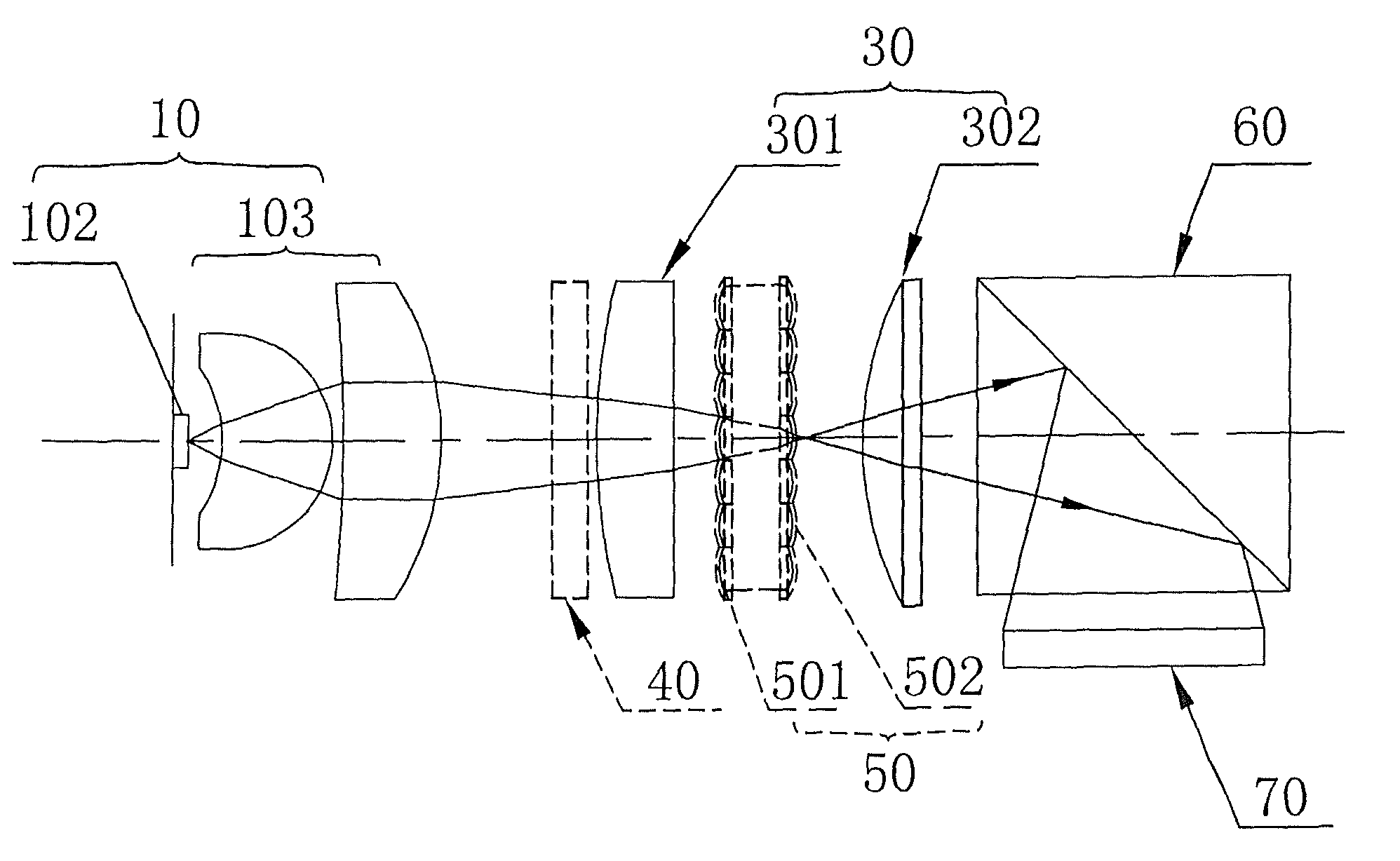
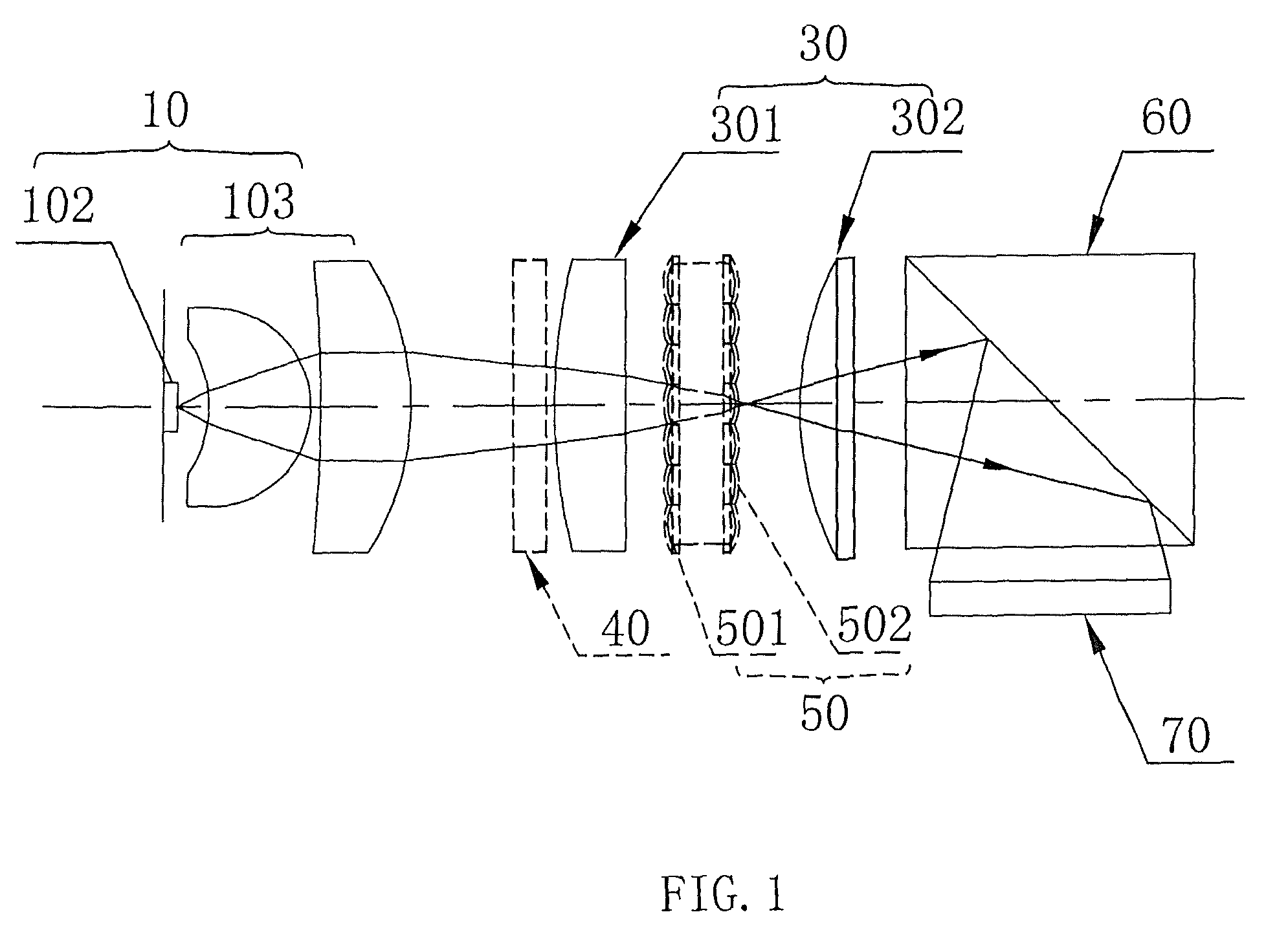
[0015]FIG. 1 is the plane structure schematic diagram of the high efficiency micro projection optical engine according to the first embodiment of present invention, which includes a light source module 10, a lens assembly 30, a polarization conversion system 40, a fly-eye lens module 50, a polarizing beam splitter 60, a micro display panel 70 and a projection lens (not shown), among which the light source module 10, the lens assembly 30, the polarization conversion system 40 and the fly-eye lens module 50 forms an illumination device.

[0016]The light source module 10 includes a light emitting element 102 and a shaping lens module 103 used to collect and shape the received light beams. In the embodiment of present invention, the light emitting element 102 is light emitting diode (LED) chip, and is used to emit light of 180 degree. Further more, a controller is connected to the LE...


PUM


Abstract

A high efficiency micro projection optical engine includes a light source module, a lens assembly, a micro display panel and a projection lens. An image of the luminous surface of light emitting elements of the light source module is formed in the vicinity of the micro display panel. The micro display panel is arranged on the path of emission light of the lens assembly to modulate incident light and obtain image light with image information. The projection lens is used to project the image information on the micro display panel and form an image onto a screen. The optical engine enhances efficiency by means of critical illumination.

Description

FIELD OF THE INVENTION[0001]Present invention relates to technique of projection display, and particularly to a high efficiency micro projection optical engine.DESCRIPTION OF THE RELATED ART[0002]During recent years, technique of liquid crystal projection has been widely used in the field of the electronic teaching, office, business, advertisement, and amusement, etc. However, as the development of technology and increasing improvement of people's living standard, liquid crystal projection of small size, light weight and high quality image is becoming the objection people seeking for.[0003]Chinese patent application publication numbered “CN1609703”, entitled “lighting diode illumination device” disclosed a projection apparatus utilizing lighting diode illumination device, which includes a plurality of LED modules composed of a red LED module, a green LED module and a blue LED module, a plurality of liquid crystal on silicon light valve panels, a plurality of polarizing beam splitter...

Claims


Application Information

Patent Timeline
Patent Type & Authority Patents(United States)
IPC IPC(8): G03B21/36
CPCG02B13/16G03B21/14H04N9/3111H04N9/315H04N9/3173H04N9/3197G02B27/1006
Inventor QU, LUJIEGAO, GUOXINLIN, JINGHE, JIANHANGWANG, XIN
Owner BUTTERFLY TECH SHENZHEN
Why Eureka
Try Eureka