Supercharge Your Innovation With Domain-Expert AI Agents!

Axial flow fan

a technology of axial flow fan and axial flow, which is applied in the direction of positive displacement liquid engine, piston pump, liquid fuel engine, etc., can solve the problems of increasing the heat generated in the coil, increasing the cost, and the inability of the electronic components to fulfill their functions properly outside the temperature rang

Active Publication Date: 2013-03-26
NIDEC CORP
View PDF11 Cites 5 Cited by
  • Summary
  • Abstract
  • Description
  • Claims
  • Application Information

AI Technical Summary

Benefits of technology

The present invention provides an axial flow fan that addresses issues with existing fans, such as reduced efficiency and excessive noise. The fan includes a stator with magnetic pole teeth and coils, a rotating shaft with a rotor magnet, an impeller, and a case with through holes. The fan also includes a substrate that connects the coils, which is located below the rotor magnet. The substrate is either placed at the bottom of the case or positioned axially below the stator. The technical effects of this design include improved fan efficiency, reduced noise, and improved air flow.

Problems solved by technology

Since normal operating temperature ranges are defined for many of the electronic components, the electronic components are unable to fulfill their functions properly outside their temperature ranges.
However, the method of applying a high voltage to the coils necessitates a booster circuit for raising the supply voltage, which leads to an increase in costs.
The method of passing a high current through the coils brings about an increase in heat generated in the coils, which leads to lowering the motor efficiency.

Method used


Image

  • Axial flow fan
  • Axial flow fan
  • Axial flow fan

Examples


first preferred embodiment

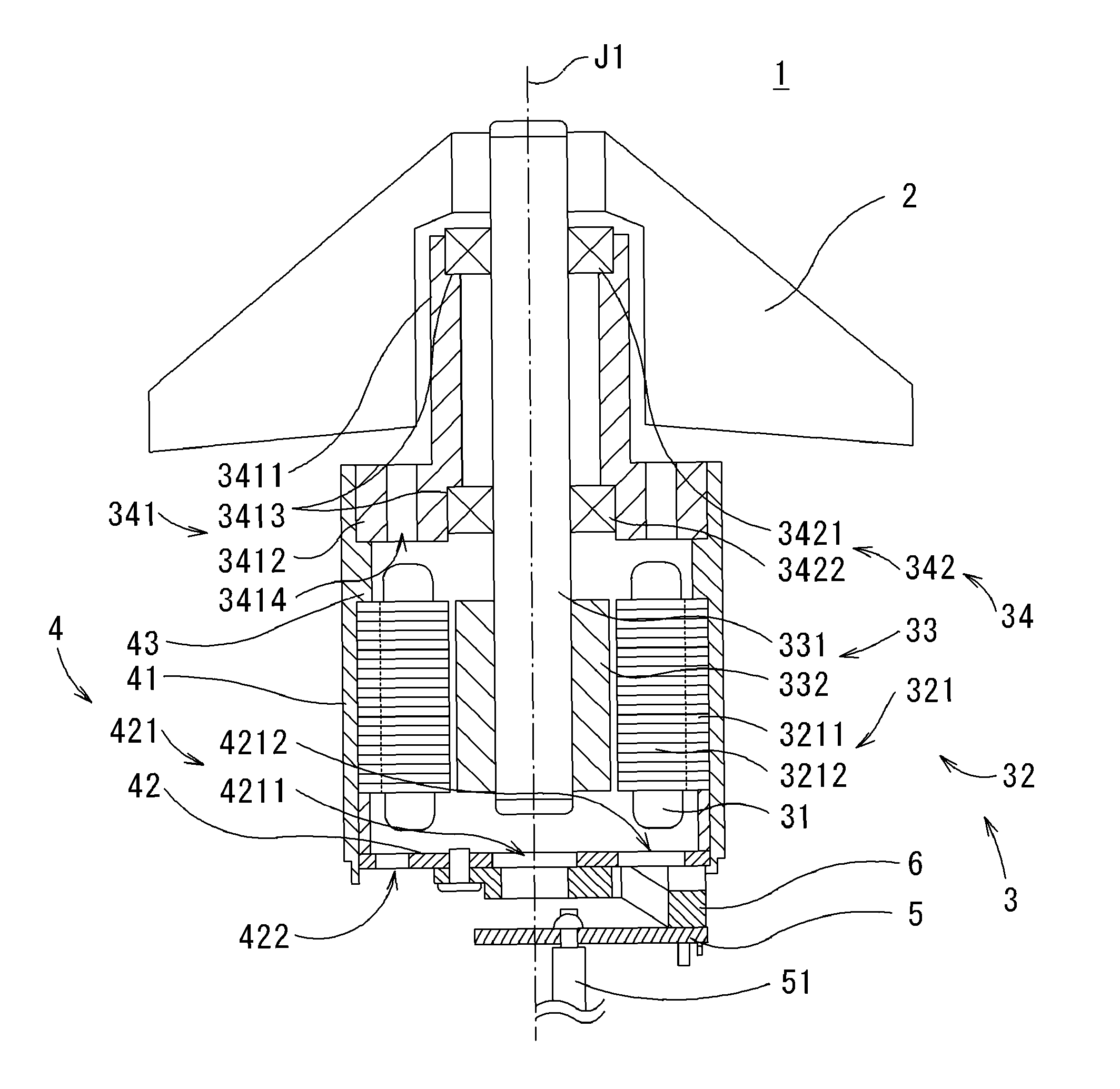
[0021]A description is provided of an axial flow fan 1 according to a first preferred embodiment of the present invention. FIG. 1 shows a longitudinal cross-section of the axial flow fan 1 according to the first preferred embodiment of the present invention, taken along a plane including a central axis J1.

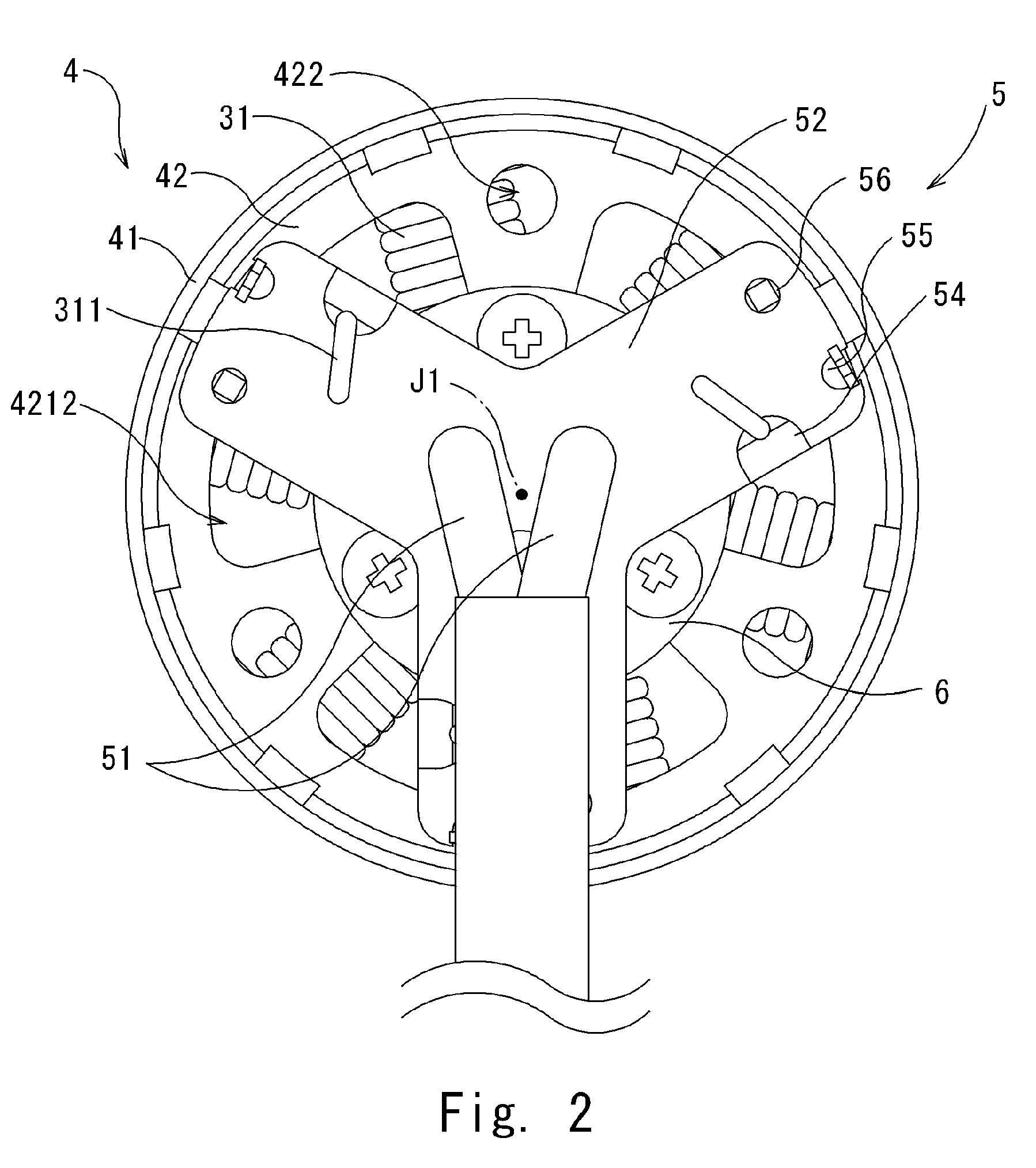
[0022]As shown in FIG. 1, the axial flow fan 1 includes an impeller 2, a motor 3, a case 4, a substrate 5, and lead wires 51. The impeller 2 rotates to produce an air flow along the central axis J1. The motor 3 is coupled to the impeller 2 to rotate the impeller 2 about the central axis J1. The case 4 holds the outer periphery of the motor 3. The substrate 5 connects ends of coils 31 that are drawn out from the motor 3. The lead wires 51 are connected to the substrate 5 and are drawn to the outside. The axial flow fan 1 according to the present preferred embodiment rotates at a rotation rate of about 10,000 rpm or higher to obtain a large air volume and is suitable as, e.g., a cool...

second preferred embodiment

[0039]Next, a description is provided below for an axial flow fan 1a according to a second preferred embodiment of the present invention. FIG. 5 shows a longitudinal cross-section of the axial flow fan 1a according to the second preferred embodiment of the present invention, taken along a plane including the central axis J1. FIG. 6 is a bottom view of the axial flow fan 1a excluding the impeller 2. As shown in FIG. 5, in the axial flow fan 1a according the present preferred embodiment, a substrate 5a is fixed to a bottom portion 42a without using the spacer 6 shown in FIGS. 1 and 4. The other elements are the same as those shown in FIG. 1, and the same reference numerals are used in the following description.

[0040]As shown in FIGS. 5 and 6, three projections 423 (indicated with broken lines in FIG. 6) that project downward are provided circumferentially at equal intervals on the bottom portion 42a at the outer peripheral side. The projections 423 preferably have a circular or substa...

third preferred embodiment

[0042]Next, a description is provided for an axial flow fan 1b according to a third preferred embodiment of the present invention. FIG. 7 shows a longitudinal cross-section of the axial flow fan 1b according to the third preferred embodiment of the present invention, taken along a plane including the central axis J1. FIG. 8 is a side view of the appearance of the axial flow fan 1b excluding the impeller 2. FIG. 9 is a bottom view of the axial flow fan 1b excluding the impeller 2. As shown in FIGS. 7 and 8, in the axial flow fan 1b according to the present preferred embodiment, a substrate 5b is fixed to a bottom portion 42b without using the spacer 6 shown in FIGS. 1 and 4, and a plurality of through holes 411b are provided in a tubular portion 41b of a case 4b. The bottom portion 42b has a plurality of through holes 421b, including a central hole 4211b and bottom holes 4212b, and a plurality of attachment holes 422b. The other elements are the same as those of FIG. 1, and the same ...


PUM


Abstract

In an axial fan including a motor, a substrate that connects the ends of a plurality of coils is disposed at a position axially under the bottom portion of a case with an axial gap therebetween. A spacer is interposed between the substrate and the bottom portion, and the substrate is fixed to the spacer. A plurality of through holes provided in the bottom portion are disposed in axial alignment with a plurality of through holes provided in the spacer. An air flow produced by rotation of an impeller at least partially passes through the interior of the case to be discharged to the outside of the case through the through holes in the bottom portion and in the spacer so that heat generated inside the motor can be efficiently transferred to the outside of the case.

Description

BACKGROUND OF THE INVENTION[0001]1. Field of the Invention[0002]The present invention relates to an axial flow fan, and more particularly, to an axial flow fan that is suitable for use as a cooling device for cooling electronic equipment.[0003]2. Description of the Related Art[0004]In recent years, an increased amount of heat is generated from apparatuses such as personal computers and servers as the capabilities of constituent electronic components are improved. Servers, in particular, contain a number of electronic components within relatively small housings, and thus the temperature within the housings rises significantly. Since normal operating temperature ranges are defined for many of the electronic components, the electronic components are unable to fulfill their functions properly outside their temperature ranges. For this reason, a cooling device with a high cooling performance is necessary in order to cool the electronic components. As such a cooling device, axial flow fan...

Claims


Application Information

Patent Timeline
Patent Type & Authority Patents(United States)
IPC IPC(8): F04B35/04
CPCF04D25/082H02K5/1735F04D25/0693H02K9/06H02K5/20H02K7/14H02K5/207F04D29/5806
Inventor YAMAMOTO, MASATOTANAKA, KENICHIADACHI, KEN
Owner NIDEC CORP
Features
  • R&D
  • Intellectual Property
  • Life Sciences
  • Materials
  • Tech Scout
  • Unparalleled Data Quality
  • Higher Quality Content
  • 60% Fewer Hallucinations
Learn More