
Method and apparatus for collection of cardiac geometry based on optical or magnetic tracking

a technology of optical or magnetic tracking and collection method, applied in the field of imaging systems, can solve the problems of various gaps in disparate images, the images collected by the wand are not registered together,

Active Publication Date: 2013-04-02
ST JUDE MEDICAL ATRIAL FIBRILLATION DIV
View PDF92 Cites 34 Cited by
  • Summary
  • Abstract
  • Description
  • Claims
  • Application Information

AI Technical Summary

Benefits of technology

The patent describes a cardiac imaging system that uses a handheld or catheter-based imaging module with an ultrasound emitter and position markers to create three-dimensional images of a patient's anatomy. The system includes a tracking and control system that senses the location and orientation of the markers and automatically aligns the images relative to a predetermined reference. The system can also use optical fiducial markers or magnetic markers for positioning and can produce a four-dimensional image that includes time. The system can be used in automatic cardiac imaging and can help guide interventional devices like catheters. The method involves attaching position markers to the imaging module and sensing the markers' location and orientation relative to a reference. The position markers can be optical fiducial markers or magnetic markers, and the system can use infrared light or magnetic emitter to sense the markers.

Problems solved by technology

A drawback of these methods is that the various images collected by the wand are not registered together.
Moreover, since the wand can be manually or even mechanically rotated, there can be various gaps in the disparate images.

Method used


Image

  • Method and apparatus for collection of cardiac geometry based on optical or magnetic tracking
  • Method and apparatus for collection of cardiac geometry based on optical or magnetic tracking
  • Method and apparatus for collection of cardiac geometry based on optical or magnetic tracking

Examples


Embodiment Construction

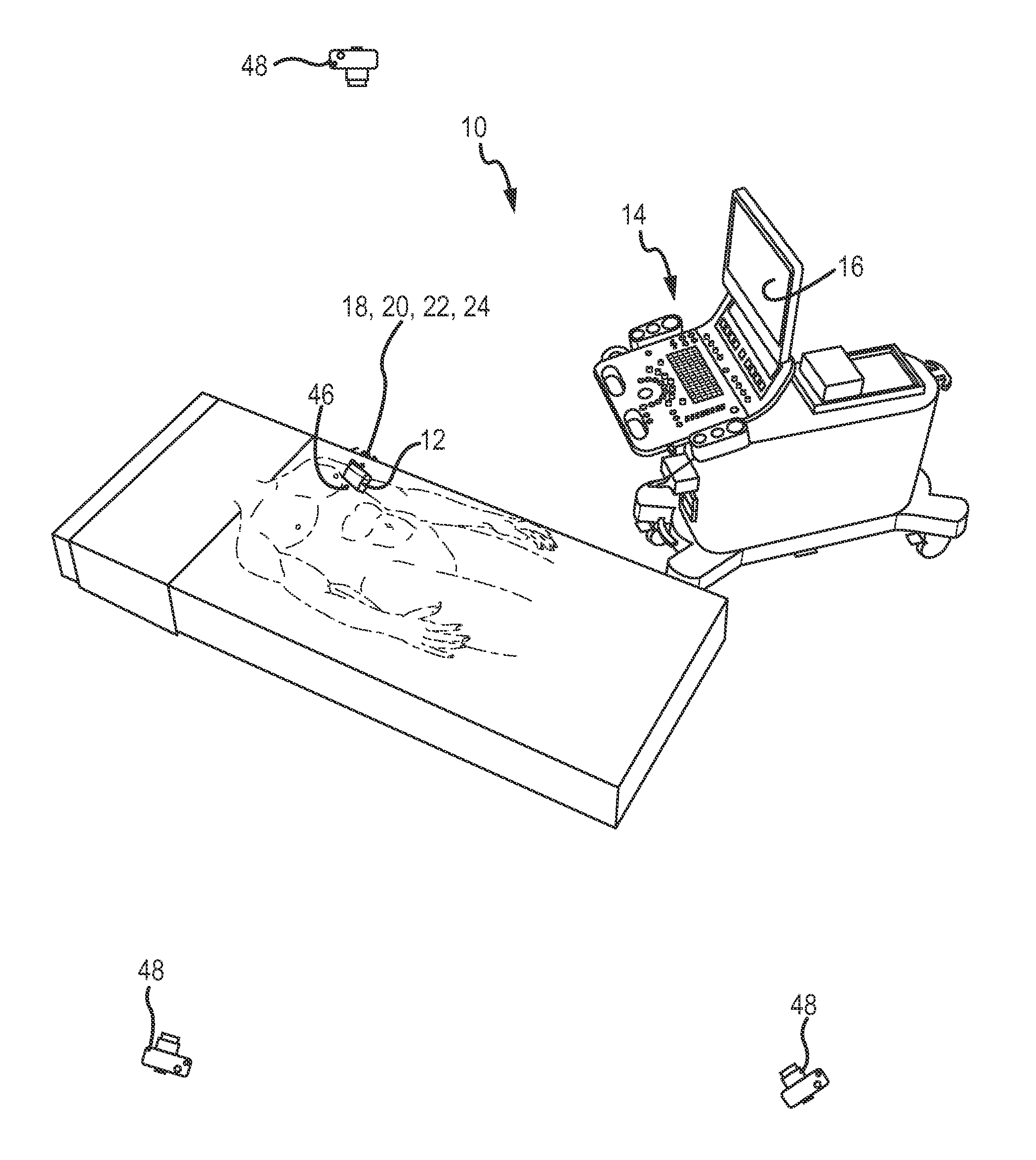
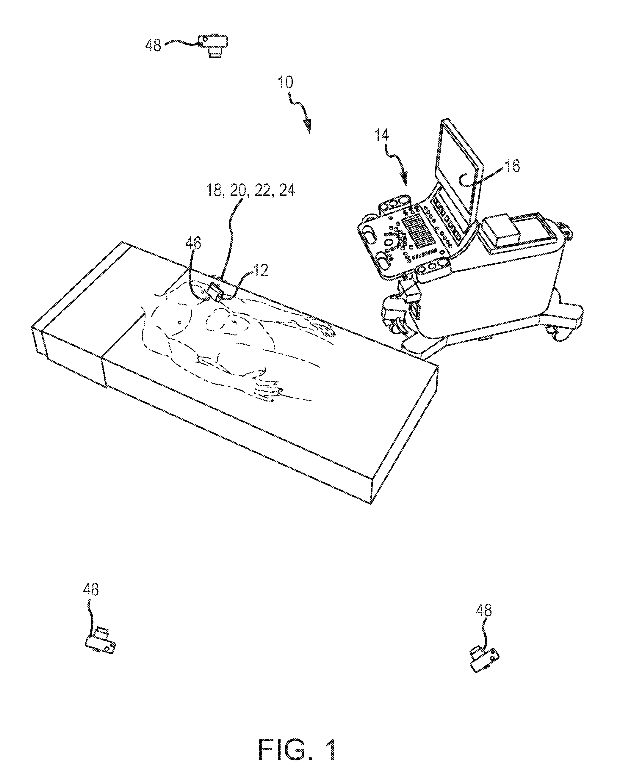
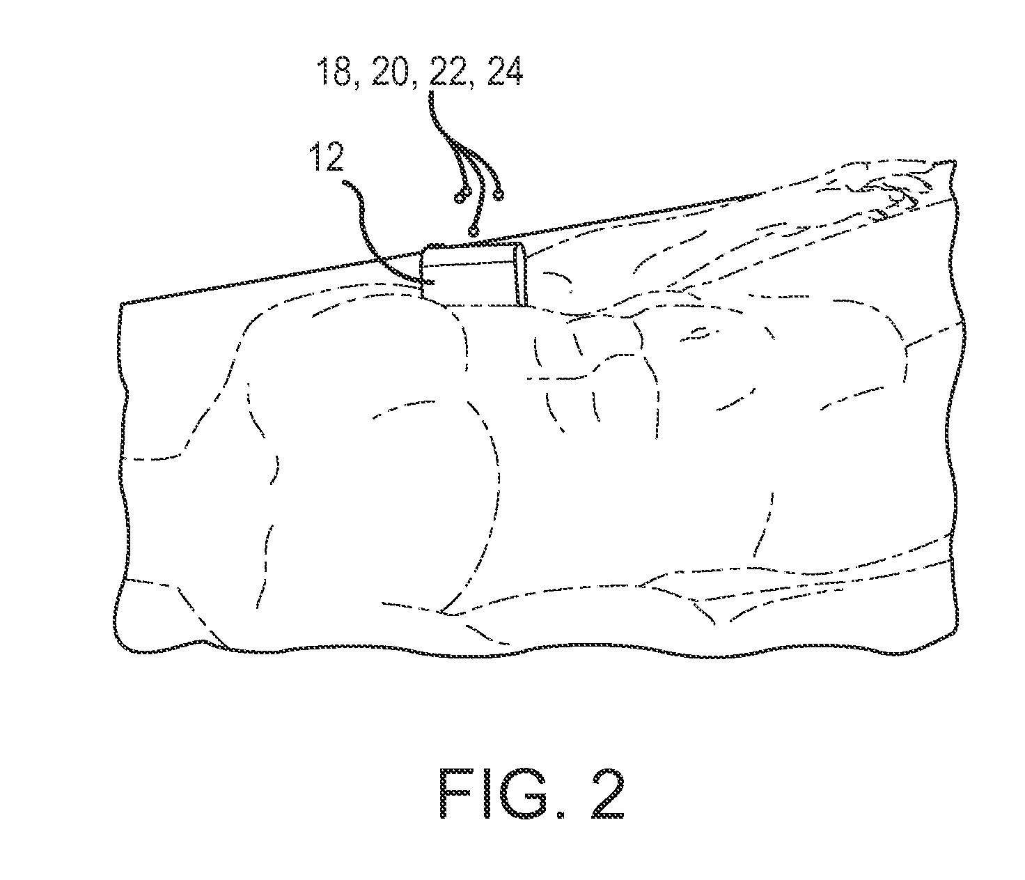
[0029]Referring now to the drawings wherein like reference numerals are used to identify identical components in the various views, FIG. 1 illustrates an optical-based imaging system 10 in accordance with the invention. Imaging system 10 may be configured to image desired internal anatomic structures of a patient, may be used to track and / or navigate interventional devices, and may be usable in combination with a robotic catheter system (e.g. disclosed in commonly owned and copending applications titled “Robotic Catheter System,”“Robotic Catheter Manipulator Assembly,”“Robotic Catheter Device Cartridge,”“Robotic Catheter Rotatable Device Cartridge,”“Robotic Catheter Input Device,”“Robotic Catheter System Including Haptic Feedback,” and “Robotic Catheter System with Dynamic Response,” the respective disclosures of which are incorporated herein by reference in their entirety). Accordingly, imaging system 10 may also be considered an “imaging and navigation” system rather than simply a...


PUM


Abstract

A cardiac imaging system including an imaging module including an ultrasound emitter and one or more position markers. A tracking and control system may include a position sensing system for sensing a location and orientation of the position marker relative to a predetermined reference. The tracking and control system may be operable with the imaging module to produce at least a three dimensional image of a patient's anatomy. A method of cardiac imaging may include operatively attaching one or more position markers to an imaging module including an ultrasound emitter. The method may further include sensing a location and orientation of the position marker relative to a predetermined reference, and producing at least a three dimensional image of a patient's anatomy by evaluating one or more images obtained by the imaging module and aligning the image(s) obtained by the imaging module relative to the location and orientation of the position marker.

Description

BACKGROUND OF THE INVENTION[0001]a. Field of the Invention[0002]The invention relates to imaging systems for use in the performance of medical diagnostic, therapeutic, mapping and ablative procedures. More particularly, the invention relates to an imaging system including optical or magnetic tracking for generating accurate 2D or 3D time varying images.[0003]b. Background Art[0004]A variety of imaging systems can be used to assist a clinician or physician in the performance of various medical diagnostic and therapeutic procedures related to different parts of the human anatomy, such as, the heart. Such imaging systems include, for example, those based on a variety of technologies, such as, wands (e.g. ultrasound), (fluoroscopy (e.g., x-rays), computed tomography (CT), magnetic resonance (MR), and intracardiac echocardiography (ICE). For ultrasound wands, an ultrasound emitter may be disposed in the wand, or in the case of catheters (e.g. ICE (intra-cardiac echo) or TEE (transesophag...

Claims


Application Information

Patent Timeline
Patent Type & Authority Patents(United States)
IPC IPC(8): A61B8/00
CPCA61B8/08A61B8/0883A61B5/06A61B8/4405A61B5/062A61B5/064
Inventor OLSON, ERIC S.
Owner ST JUDE MEDICAL ATRIAL FIBRILLATION DIV
Learn More