

Cables and connector assemblies employing a furcation tube(s) for radio-frequency identification (RFID)-equipped connectors, and related systems and methods
a technology of furcation tubes and connectors, applied in the direction of optics, instruments, optical elements, etc., can solve the problems of large number of cables and connections that are still difficult to manage, and the identification of proper connectors (e.g., plugs and sockets, mated) for setting up and maintaining the system accordingly becomes more complex, so as to avoid snagging of antenna wires
- Summary
- Abstract
- Description
- Claims
- Application Information
AI Technical Summary
Benefits of technology
Problems solved by technology
Method used
Image

Examples
Embodiment Construction
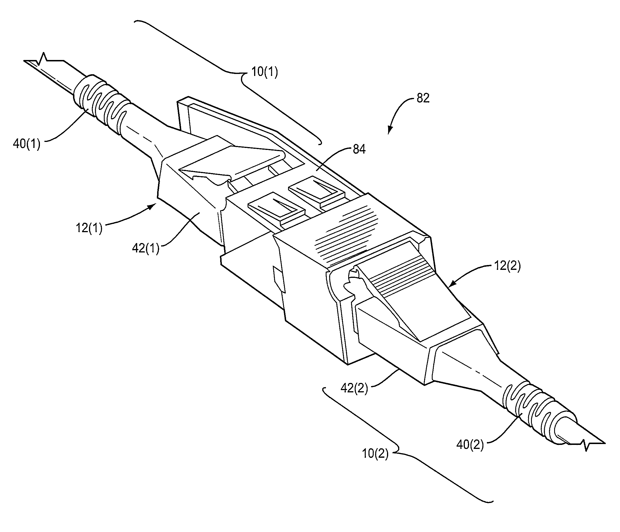
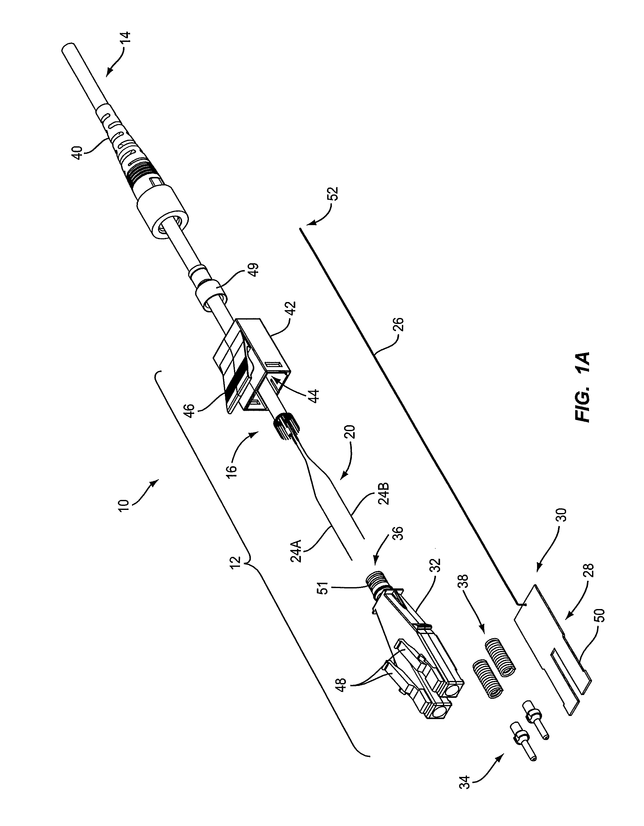
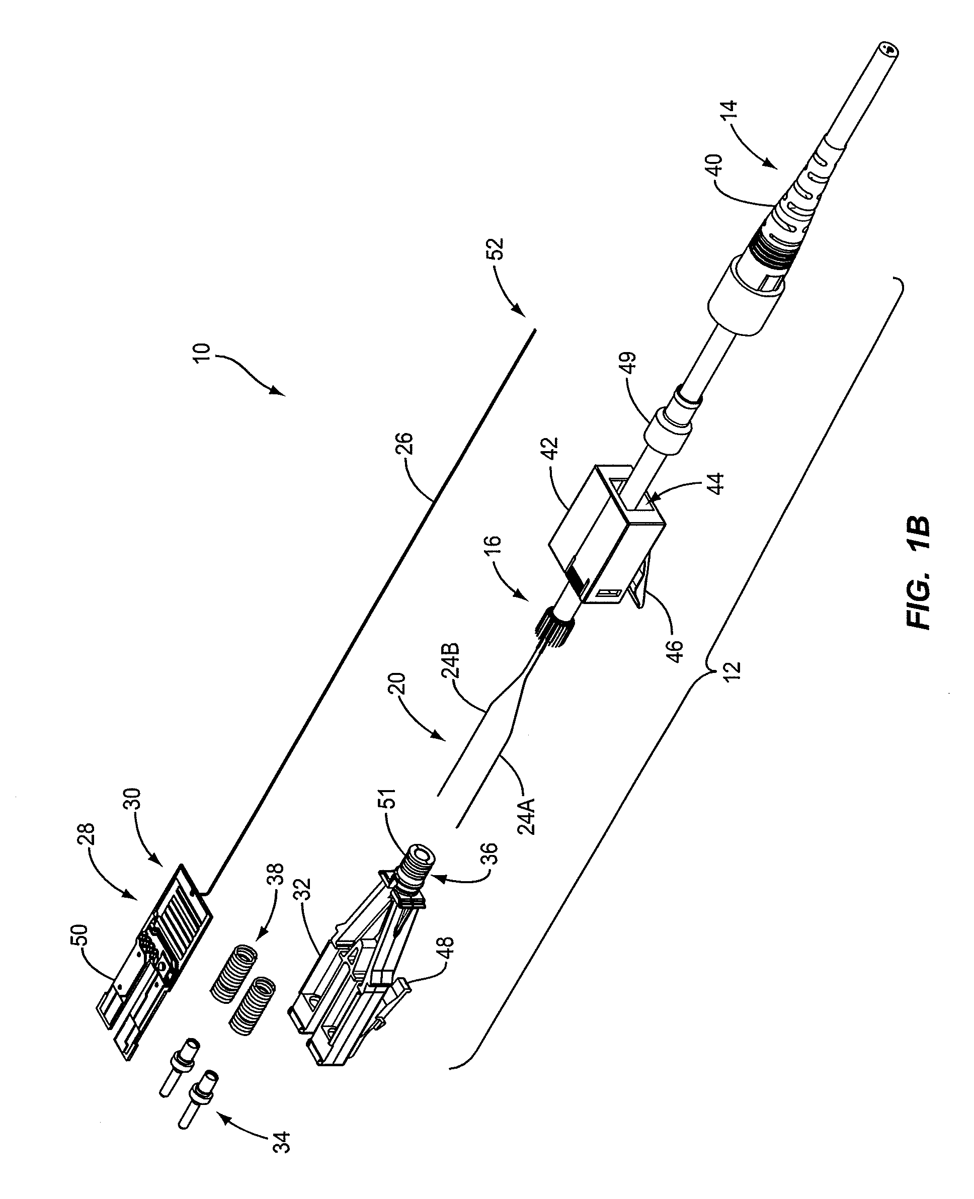
[0010]Embodiments disclosed in the detailed description include cables and connector assemblies employing a furcation tube(s) for radio-frequency identification (RFID)-equipped connectors, and related systems and methods. The cables, connector assemblies, and related systems and methods provide for an antenna wire that either forms all or a portion of an antenna for an RFID transponder or tag. The RFID tag may be provided as part of the connector assembly. If the length of the antenna wire extends beyond or outside of the connector housing, embodiments disclosed herein provide for the antenna wire to be packaged inside at least one furcation tube disposed in a cable carrying a communication line(s) and forming part of the connector assembly. In this manner, the antenna wire is secured inside the cable of the cable assembly. The cable assembly provides a rugged assembly internal to the cable to protect the antenna wire from breakage. For example, bend relief provided as part of the c...
PUM
| Property | Measurement | Unit |
|---|---|---|
| length | aaaaa | aaaaa |
| length | aaaaa | aaaaa |
| length | aaaaa | aaaaa |
Abstract
Description
Claims
Application Information