
Multi-display mirror system and method for expanded view around a vehicle

a multi-display mirror and vehicle technology, applied in the field of multi-display mirror system and expanded view around a vehicle, can solve the problems of preventing the user from fully utilizing such an arrangement, requiring bulb mounting away from the display, and limited life and heat generation

Active Publication Date: 2013-04-02
GENTEX CORP
View PDF60 Cites 80 Cited by
  • Summary
  • Abstract
  • Description
  • Claims
  • Application Information

AI Technical Summary

Benefits of technology

The patent text discusses the use of LED backlighting in LCD displays and the challenges in integrating them into various products. The technical problem addressed in the patent is how to effectively use LED technology in small LCD displays to achieve the right balance of cost and performance, including the need for software control to adjust brightness and compensate for ambient light conditions. The text also mentions the use of small color LCD displays in automotive applications, such as in an automotive mirror, and the drawbacks of using cameras on the sides of the vehicle for providing video information to displays in the mirror. The invention aims to provide a solution to these issues and improve the overall performance of LED backlighting in LCD displays.

Problems solved by technology

Although incandescent backlighting can be used when very high brightness is desired, the use of incandescent bulbs has many drawbacks, such as limited life and the amount of heat generated, which often means that the bulb needs to be mounted away from the display.
One drawback of this type of system is that the information is dedicated from one camera to one display, preventing the user from fully utilizing such an arrangement.

Method used


Image

  • Multi-display mirror system and method for expanded view around a vehicle
  • Multi-display mirror system and method for expanded view around a vehicle
  • Multi-display mirror system and method for expanded view around a vehicle

Examples


Embodiment Construction

[0040]Before describing in detail embodiments that are in accordance with the present invention, it should be observed that the embodiments reside primarily in combinations of method steps and apparatus components related to an automotive mirror assembly including backlighting for an LCD. Accordingly, the apparatus components and method steps have been represented where appropriate by conventional symbols in the drawings, showing only those specific details that are pertinent to understanding the embodiments of the present invention so as not to obscure the disclosure with details that will be readily apparent to those of ordinary skill in the art having the benefit of the description herein.

[0041]In this document, relational terms such as first and second, top and bottom, and the like may be used solely to distinguish one entity or action from another entity or action without necessarily requiring or implying any actual such relationship or order between such entities or actions. T...


PUM

PropertyMeasurementUnit
period of timeaaaaaaaaaa
distanceaaaaaaaaaa
distancesaaaaaaaaaa

Abstract

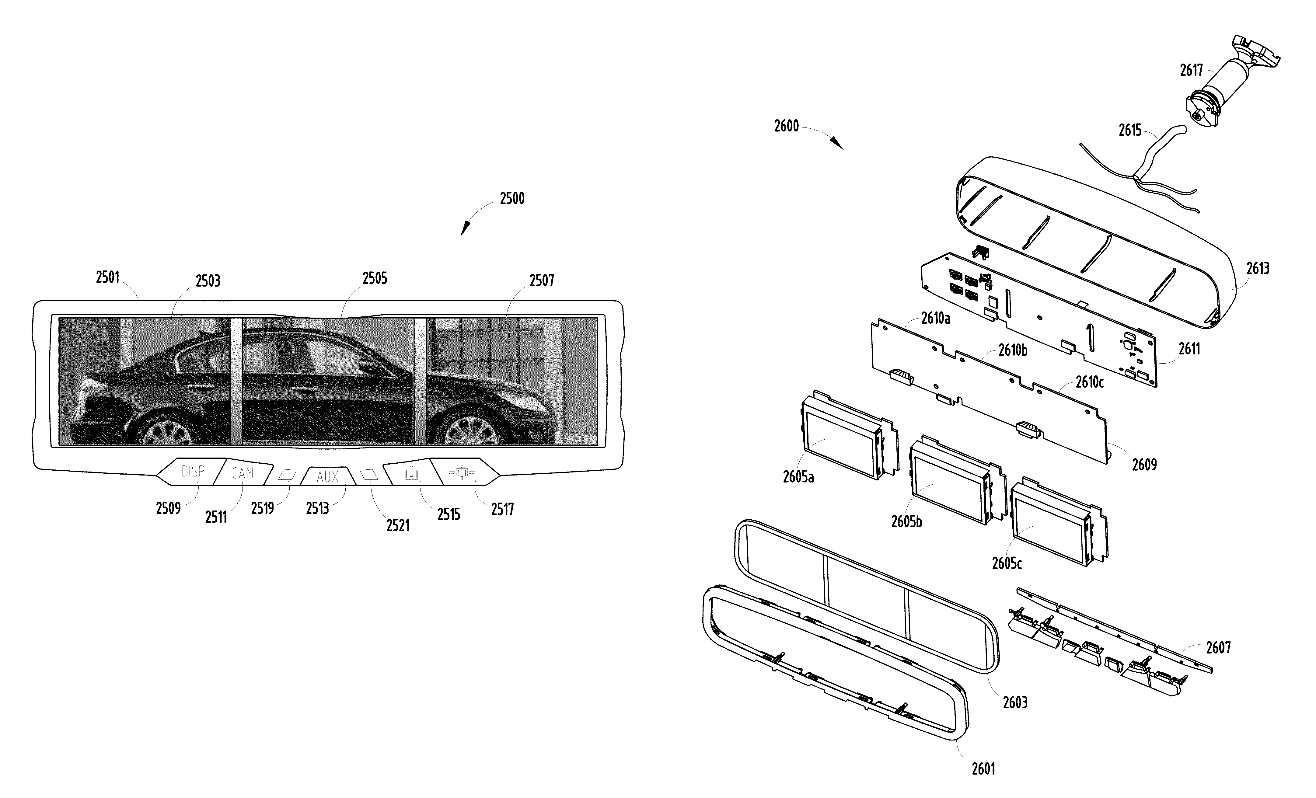
A multi-display vehicular rearview mirror system (2600) and method includes an electrochromic (EC) glass element (2603) and a plurality of liquid crystal displays (LCDs) (2605a, 2605b, 2605c) positioned behind EC element (2603). A plurality of light emitting diodes (LEDs) (2610a, 2610b, 2610c) are used for providing backlighting for each respective LCD of the plurality of LCDs such that the LCDs utilize a plurality of imaging devices (2717, 2719, 2721) for forming substantially a single image across the plurality of LCDs (2605a, 2605b, 2605c).

Description

PRIORITY TO RELATED APPLICATIONS[0001]This application is a continuation-in-part of U.S. patent application Ser. No. 12 / 367,143 entitled “A VEHICULAR REARVIEW MIRROR ASSEMBLY INCLUDING INTEGRATED BACKLIGHTING FOR A LIQUID CRYSTAL DISPLAY (LCD)” filed Feb. 6, 2009 now U.S. Pat. No. 8,237,909 and commonly assigned to Gentex Corporation and claims priority under 35 U.S.C. §120.BACKGROUND OF THE INVENTION[0002]A backlight is a form of illumination used in liquid crystal displays (LCDs). Backlights illuminate the LCD from the side or back of the display panel, unlike front lights, which are placed in front of the LCD. Backlights are used in small displays to increase readability in low light conditions and in computer displays and LCD televisions to produce light in a manner similar to a cathode ray tube (CRT) display. The typical LCD backlight has traditionally been cold cathode fluorescent lamps (CCFLs). Increasingly, however, light-emitting diodes (LEDs) are becoming the predominant b...

Claims


Application Information

Patent Timeline
Patent Type & Authority Patents(United States)
IPC IPC(8): G02F1/13G02F1/133
CPCB60R1/12B60R2001/1253G02F1/13336G02F2201/44
Inventor LEE, ETHAN J.LEE, DANIEL B.HENDRICKS, MICHAEL G.ROTH, MARK R.MYERS, CRAIG R.POE, G. BRUCEBLAKER, DAVID A.SCHAUDEL, CARSTENVANVUUREN, MARK A.VANDERPLOEG, JOHN A.
Owner GENTEX CORP
Learn More