Computer readable medium and exposure method
a technology of computer readable medium and exposure method, which is applied in the field of computer readable medium and an exposure method, can solve the problems of increasing the difficulty level of exposure, wasting time and cost, and wasting experiments to confirm the possibility of exposure, etc., and achieves the effect of short tim
- Summary
- Abstract
- Description
- Claims
- Application Information
AI Technical Summary
Benefits of technology
Problems solved by technology
Method used
Image
Examples
first embodiment
[0168]In a first embodiment, Xeon® 32 bit was used as a CPU included in a control unit 20 of a processing apparatus 1, and a memory of about 2 Gbytes was used as a storage unit 40. An aerial image calculation program 420 was created using MATLAB®. The time in calculating an aerial image 409 while dividing the effective light source was compared with the time in calculating the aerial image 409 without dividing the effective light source.
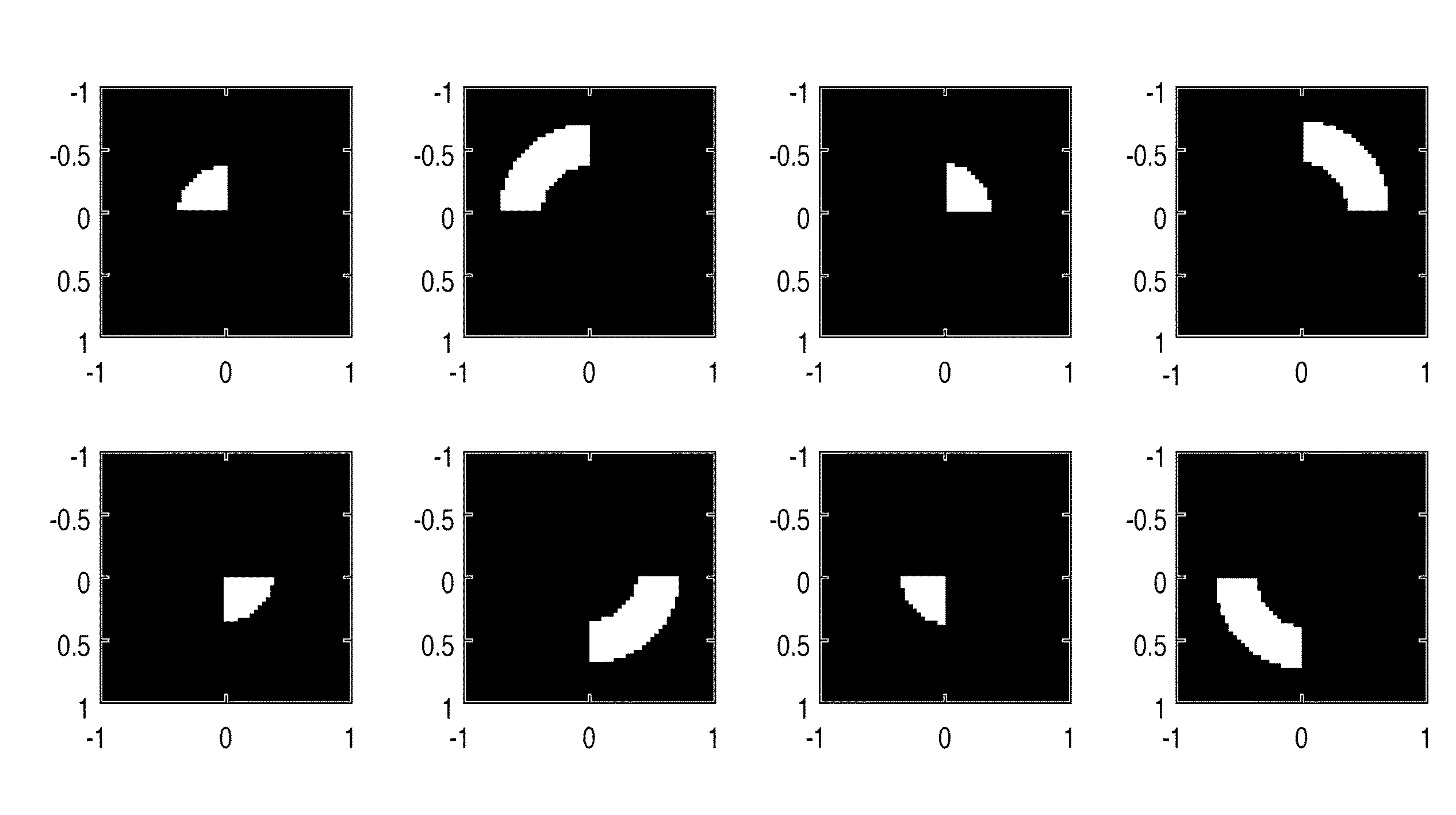
[0169]In the first embodiment, assume that the NA of the projection optical system of the exposure apparatus is 0.73 (corresponding to NA information 403), and the wavelength of exposure light is 248 nm (corresponding to λ information 404). The projection optical system has no aberration (corresponding to aberration information 405), the illumination light has no polarization (corresponding to polarization information 406), and a resist to be applied to a wafer is not taken into consideration (corresponding to resist information 407). Quadrupole illu...
second embodiment
[0174]In a second embodiment, Xeon® 32 bit was used as a CPU included in a control unit 20 of a processing apparatus 1, and a memory of about 2 Gbytes was used as a storage unit 40. An aerial image calculation program 420 was created using MATLAB®. The time in calculating an aerial image 409 while dividing the effective light source was compared with the time in calculating the aerial image 409 without dividing the effective light source.
[0175]In the second embodiment, assume that the NA of the projection optical system of the exposure apparatus is 0.73 (corresponding to NA information 403), and the wavelength of exposure light is 248 nm (corresponding to λ information 404). The projection optical system has no aberration (corresponding to aberration information 405), the illumination light has no polarization (corresponding to polarization information 406), and a resist to be applied to a wafer is not taken into consideration (corresponding to resist information 407). Circular illu...
fourth embodiment
[0185]In a fourth embodiment, an exposure apparatus 100 which executes exposure processing by adjusting exposure conditions based on an aerial image (a light intensity distribution formed on the image plane of the projection optical system) calculated by the above-described processing apparatus 1 will be described. FIG. 14 is a schematic block diagram showing the arrangement of the exposure apparatus 100.
[0186]The exposure apparatus 100 is an immersion exposure apparatus which transfers the pattern of a mask 130 onto a wafer 150 by step-and-scan via a liquid LW supplied between a projection optical system 140 and the wafer 150. The exposure apparatus 100 can also use a step-and-repeat method or any other exposure method.
[0187]As shown in FIG. 14, the exposure apparatus 100 includes an illumination optical system 120, a mask stage 135 on which the mask 130 is placed, the projection optical system 140, a wafer stage 155 on which the wafer 150 is placed, a liquid supply / recovery unit 1...
PUM
| Property | Measurement | Unit |
|---|---|---|
| wavelength | aaaaa | aaaaa |
| time | aaaaa | aaaaa |
| time | aaaaa | aaaaa |
Abstract
Description
Claims
Application Information
 - R&D
- Intellectual Property
- Life Sciences
- Materials
- Tech Scout
- Unparalleled Data Quality
- Higher Quality Content
- 60% Fewer Hallucinations
Browse by: Latest US Patents, China's latest patents, Technical Efficacy Thesaurus, Application Domain, Technology Topic, Popular Technical Reports.
© 2025 PatSnap. All rights reserved.Legal|Privacy policy|Modern Slavery Act Transparency Statement|Sitemap|About US| Contact US: help@patsnap.com


