Liquid crystal display backlight device and liquid crystal display

a backlight device and liquid crystal display technology, applied in lighting and heating apparatus, planar/plate-like light guides, instruments, etc., can solve the problems of poor diffraction efficiency of hologram mirror reflectance depending on wavelength, uneven color distribution, and uneven brightness, so as to reduce light quantity loss and ensure uniform brightness

Inactive Publication Date: 2013-04-09
PANASONIC CORP
View PDF9 Cites 9 Cited by
  • Summary
  • Abstract
  • Description
  • Claims
  • Application Information

AI Technical Summary

Benefits of technology

[0011]With the foregoing in view, it is an object of the present invention to provide a liquid crystal display backlight device and liquid crystal display that can suppress the light quantity loss and ensure uniformity of brightness.
[0014]According to the present invention, the laser light is transformed into planar laser light by reflecting the linear laser light by the planar reflection surface disposed on the light guiding plate, therefore light quantity loss can be suppressed, and brightness can be uniform.

Problems solved by technology

However in the case of a system where laser light are reflected using a hologram mirror, as disclosed in Patent Literature 1, if three colors: R (red), G (green) and B (blue) are used as the laser light source, the reflection direction by the hologram mirror is different depending on the color, which may generate uneven color in the distribution of light finally emitted from the light guiding plate.
For example, if the laser light has a Gaussian profile light quantity distribution, the brightness in the center area of the light guiding plate increases, which means that only uneven brightness can be implemented, which is not acceptable.
Generally the reflectance of a hologram mirror has poor diffraction efficiency depending on the wavelength, and generates a light quantity loss.
Furthermore the half mirrors are used for the configuration to two-dimensionally reflect the laser light, which means that the reflectance errors of half mirrors are reflected in the brightness distribution.
In order to irradiate a large area panel with slim construction, many half mirrors, of which respective transmittance characteristics have subtle differences, are required, which makes manufacturing very difficult and increases cost, and generates many other problems, so it is therefore very impractical.
Even if this light is reflected using a reflection element or the like, the laser light that propagates horizontally continuously propagates for a long distance while being reflected, and generates light quantity loss due to the absorption of the light guiding plate.
If the laser light spreads and enters the entrance of the light guiding plate, brightness around the entrance increases and generates uneven brightness, so this system also has many problems.

Method used


Image

  • Liquid crystal display backlight device and liquid crystal display
  • Liquid crystal display backlight device and liquid crystal display
  • Liquid crystal display backlight device and liquid crystal display

Examples


embodiment 1

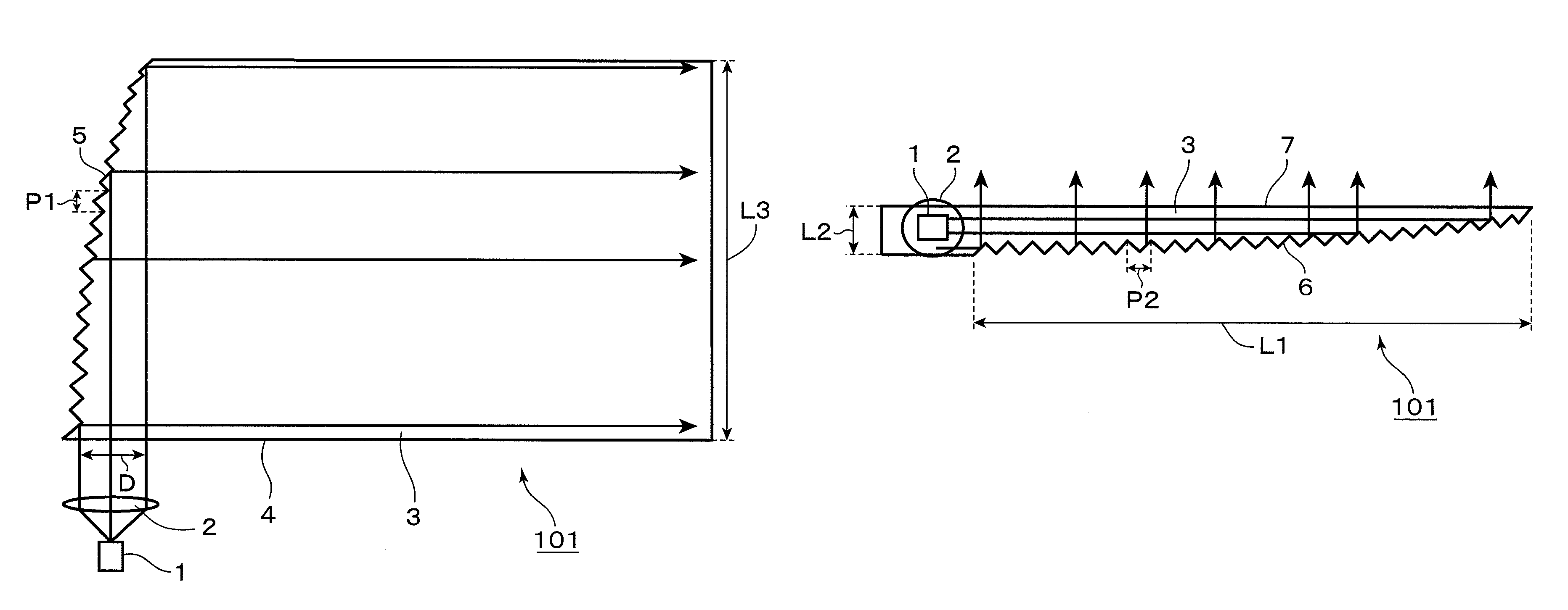
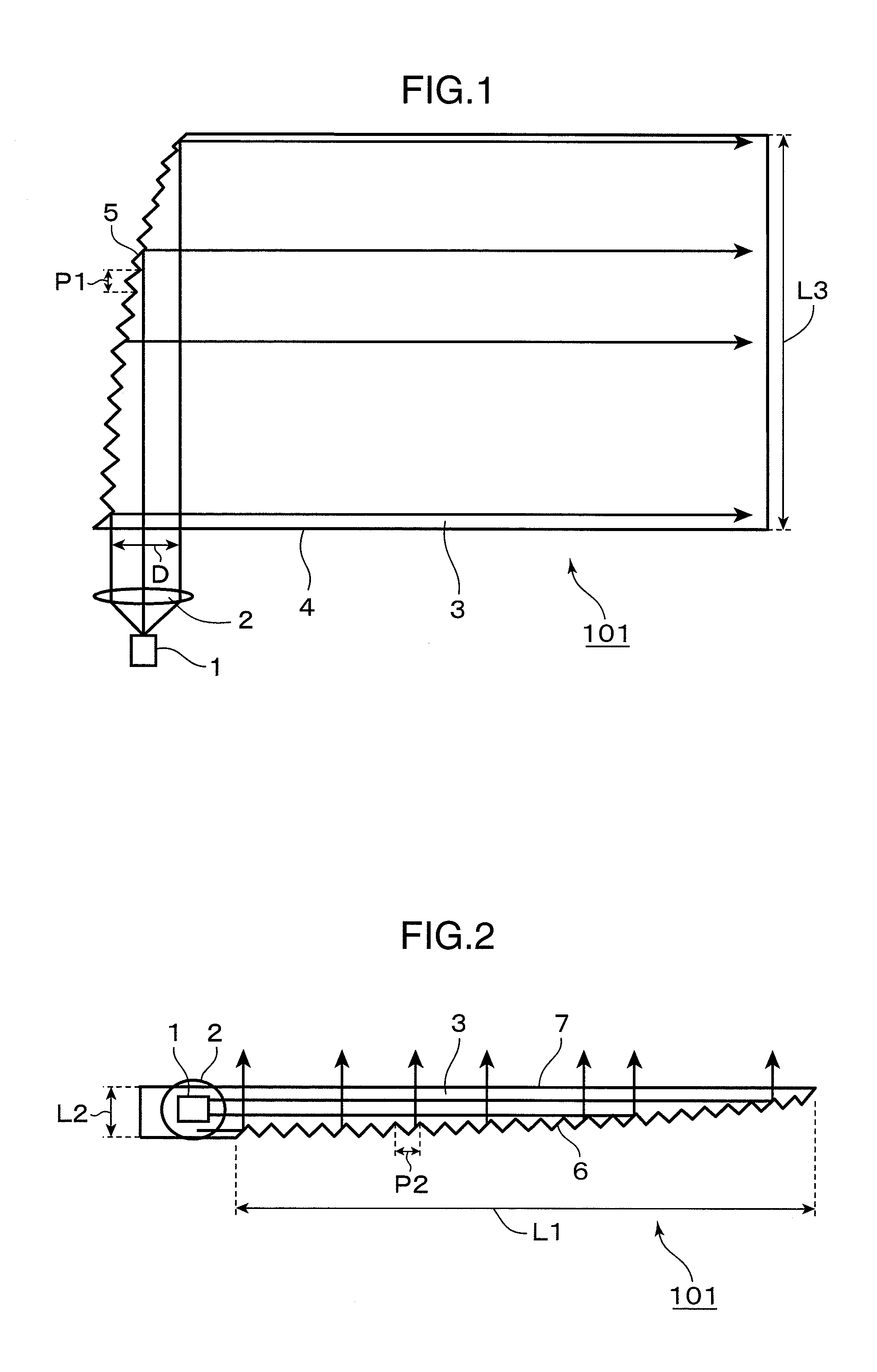
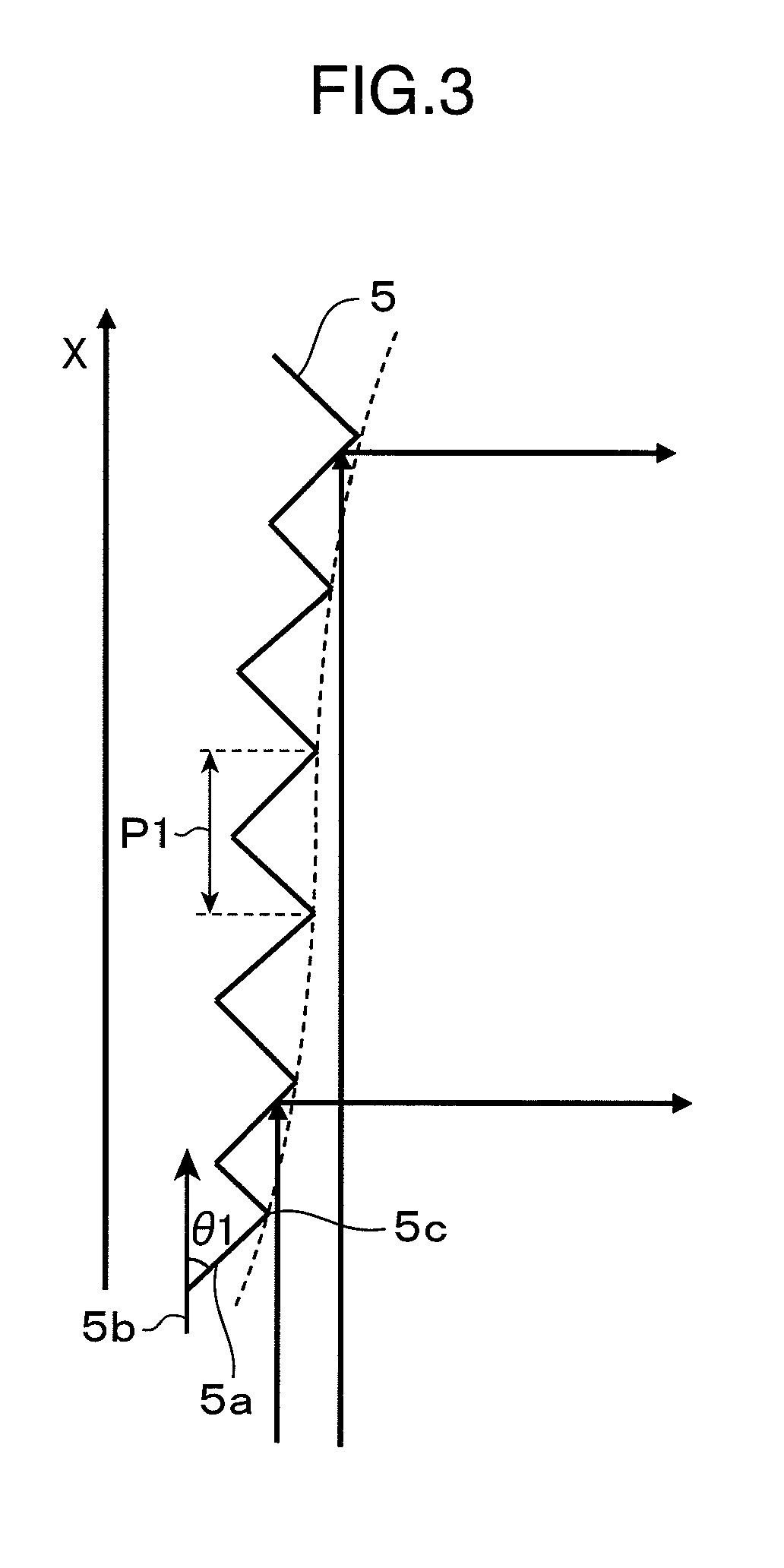
[0046]FIG. 1 is a front view depicting a configuration of an LCD backlight device according to Embodiment 1 of the present invention, and FIG. 2 is a side view depicting a configuration of the LCD backlight device according to Embodiment 1 of the present invention. FIG. 2 is a diagram depicting the LCD backlight device viewed from the laser light source side as shown in FIG. 1. The LCD backlight device 101 according to Embodiment 1 is comprised of only three components: that is a laser light source 1, a collimator lens 2 and a light guiding plate 3.

[0047]The operation of the LCD backlight device 101 according to Embodiment 1 will now be described. Laser light emitted from the laser light source 1 is transformed into approximately parallel light by the collimator lens 2. The laser light transformed into approximately parallel light enters into the light guiding plate 3 via a first side face 4 of the light guiding plate 3. The laser light enters into the light guiding plate 3 from the...

embodiment 2

[0099]FIG. 15 is a front view depicting a configuration of an LCD backlight device according to Embodiment 2 of the present invention, and FIG. 16 is a side view depicting a configuration of the LCD backlight device according to Embodiment 2 of the present invention. FIG. 16 is a diagram depicting the LCD backlight device shown in FIG. 15 viewed from the laser light source side. The LCD backlight device 201 according to Embodiment 2 is comprised of only four components, that is, a laser light source 31, collimator lens 32, light guiding plate 33 and light guiding bar 34.

[0100]Operation of the LCD backlight device 201 according to Embodiment 2 will now be described. Laser light emitted from the laser light source 31 is transformed into approximately parallel light by the collimator lens 32. The laser light transformed into approximately parallel lights enters into the light guiding bar 34 via a laser light entrance surface 35 of the light guiding bar 34. The laser light which entered...

embodiment 3

[0127]FIG. 22 is a front view depicting a configuration of an LCD backlight device according to Embodiment 3 of the present invention, and FIG. 23 is a side view depicting a configuration of the LCD backlight device according to Embodiment 3 of the present invention. FIG. 23 is a diagram depicting the LCD backlight device, shown in FIG. 22, viewed from the laser light source side. The LCD backlight device 301 according to Embodiment 3 is comprised of a laser light source 50, collimator lens 51, free-form surface mirror 52 and light guiding plate 54, and a prism array 53 is formed on a laser light entrance surface 541 of the light guiding plate 54.

[0128]The operation of the LCD backlight device 301 according to Embodiment 3 will now be described. Laser light emitted from the laser light source 50 is transformed into approximately parallel light by the collimator lens 51. The laser light transformed into approximately parallel light enters the free-form surface mirror 52. The form of ...


PUM

PropertyMeasurementUnit
angle θ1aaaaaaaaaa
angle θ1aaaaaaaaaa
angle θ2aaaaaaaaaa

Abstract

It is aimed to provide an LCD backlight device and liquid crystal display that can suppress light quantity loss and ensure uniform brightness.An LCD backlight device 101 has a laser light source 1 that emits laser light, and a light guiding plate 3 that transforms the laser light from the laser light source 1 into linear laser light, and transforms the linear laser light into a planar laser light, and emits the planar laser light, and the light guiding plate 3 has a third side face 6 that transforms the linear laser light into the planar laser light by reflecting the linear laser light by a plurality of reflection surfaces that are formed along the entrance direction of the linear laser light.

Description

TECHNICAL FIELD[0001]The present invention relates to an LCD (liquid crystal display) backlight device using three color light sources, which are R (red), G (green) and B (blue), and a liquid display device using this LCD backlight device.BACKGROUND ART[0002]Display devices have an emission type display device that can self-emit, such as an organic emission display device and plasma display device, but a light receiving type display device, that cannot self-emit and requires another light source, such as a liquid crystal display device.[0003]A general liquid crystal display device has two display panels having electric field generation electrodes and a liquid crystal layer having dielectric constant anisotropy. In such a liquid crystal display device, an electric field is generated in the liquid crystal layer by applying voltage to the electric field generation electrodes, and the intensity of this electric field is adjusted by changing the voltage so as to generate light valve, and...

Claims


Application Information

Patent Timeline
Patent Type & Authority Patents(United States)
IPC IPC(8): G02F1/1335
CPCG02B6/0016G02B6/0025G02B6/0028G02B6/0038G02B6/0018G02B6/0046
Inventor SHIKII, SHINICHIMIZUSHIMA, TETSUROITOH, TATSUOKUROZUKA, AKIRANAGATA, TAKAYUKIYAMAMOTO, KAZUHISA
Owner PANASONIC CORP
Why Eureka
Try Eureka