

Solar cell module
a solar cell and module technology, applied in the direction of heat collector mounting/support, pv power plants, light and heating apparatus, etc., can solve the problem that the rigidity may not be sufficiently assured with a conventional protective frame, and achieve the effect of improving the strength of the fram
- Summary
- Abstract
- Description
- Claims
- Application Information
AI Technical Summary
Benefits of technology
Problems solved by technology
Method used
Image

Examples
first embodiment
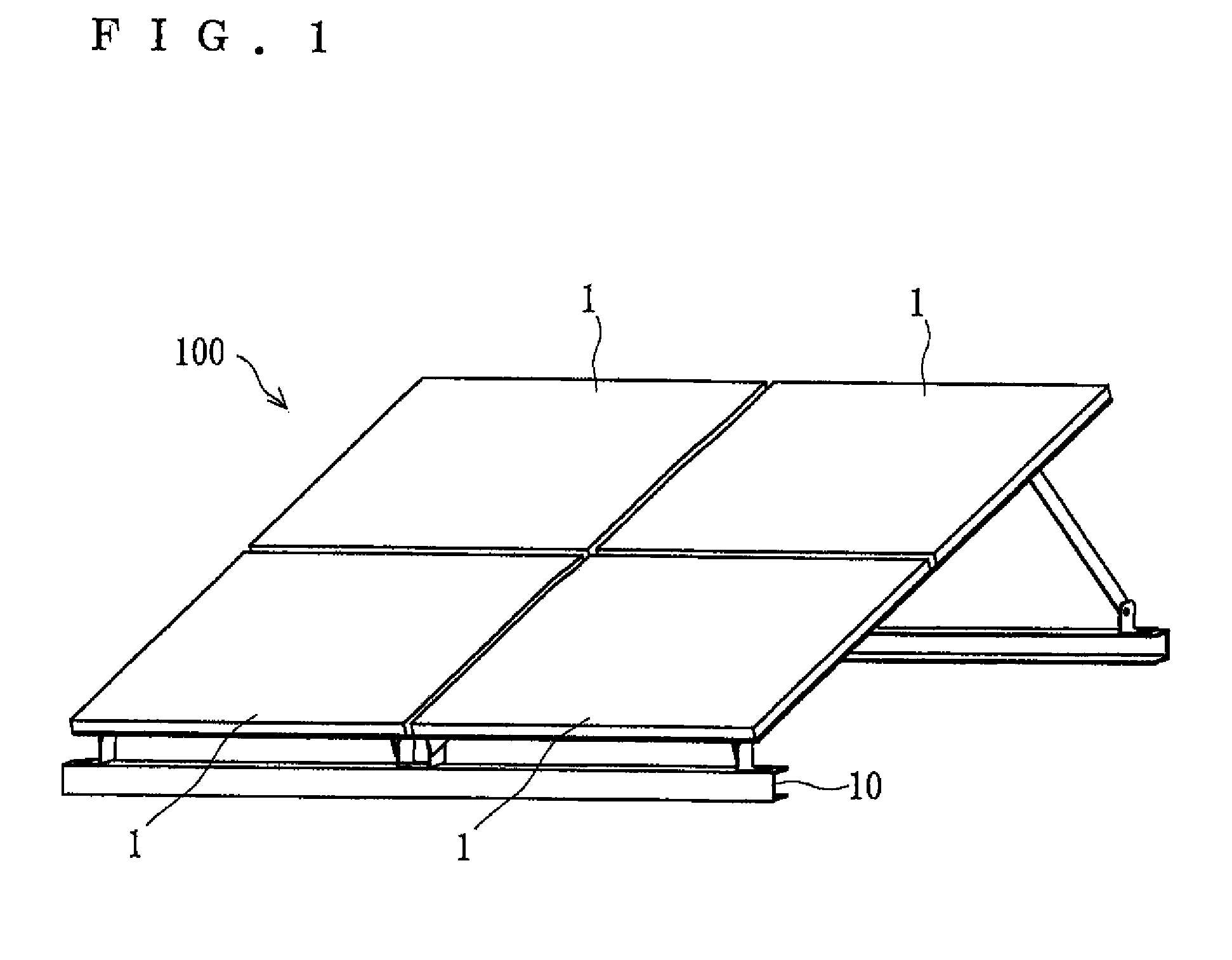
[0020]As shown in FIG. 1, a photovoltaic system 100 includes solar cell modules 1 and a platform 10 that holds the solar cell modules 1. The photovoltaic system 100 is installed in various places. For example, such installation places include a roof of a building and the ground in a site of a factory.
[0021]A periphery of the solar cell module 1 is mounted to the platform 10. The platform 10 is made of, for example, metal, light metal such as stainless steel, iron and aluminum, resin or wood.
Solar Cell Module
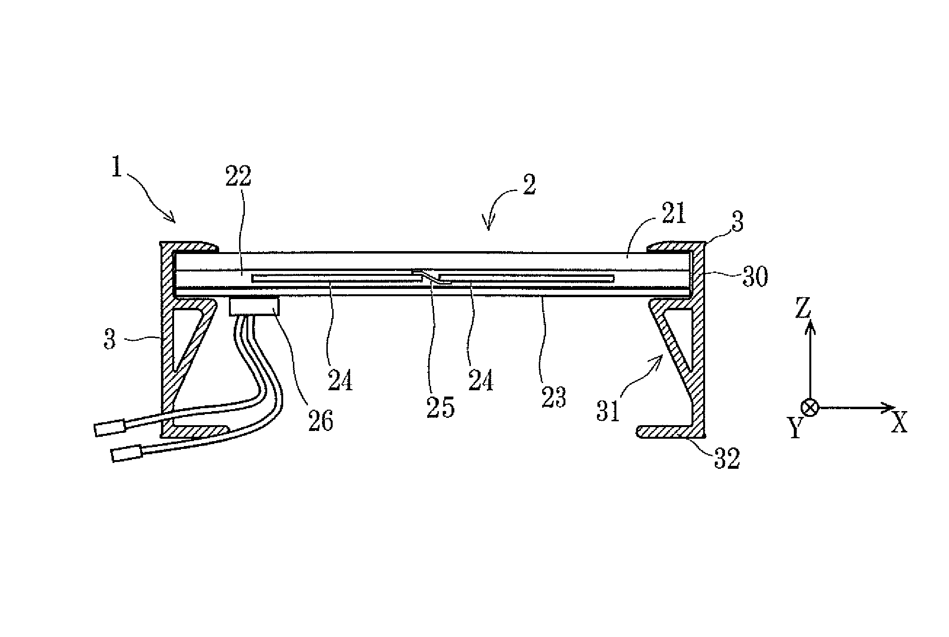
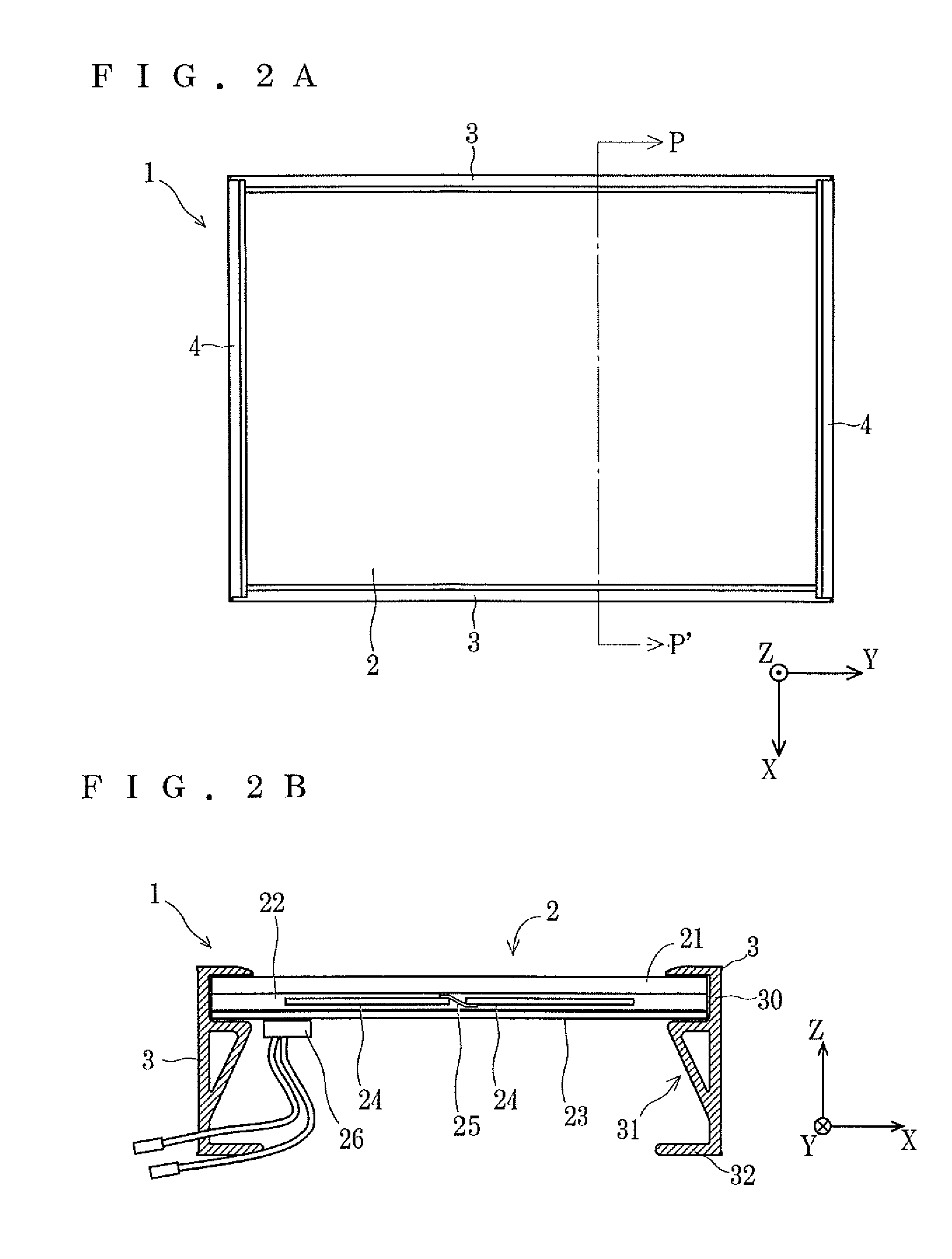
[0022]As shown in FIG. 2A, the solar cell module 1 includes a solar cell panel 2 having a rectangular flat plate shape, and a group of four frames (first frames 3 and second frames 4) mounted to the periphery of the solar cell panel 2. The first frames 3 are mounted to a pair of sides of the solar cell panel 2 that are opposed to each other, and the second frames 4 are mounted to the other pair of sides opposed to each other.
[0023]Note that in FIGS. 2A and 2B and the following dr...
second embodiment
[0049]A solar cell module 1b according to a second embodiment of the present invention is described with reference to FIG. 8. Note that the elements having similar functions as those of the first embodiment are denoted by the same numerical references, and description thereof is omitted. The same holds true for the respective embodiments below.
[0050]An annular part 31b of a first frame 3b used in the solar cell module 1b is composed of a third part 313b having a curved shape including a plurality of bending parts in cross section (curved shape having two bending parts in FIG. 8) in place of the third part 313 of the first frame 3 and a fourth part 316 that is connected to the third part 313b in a link part 37b and is connected to the second part 312b in a substantially perpendicular manner. The annular part 31b has a space 71b therein.
[0051]Here, a virtual line D linking the connecting portions (connecting parts 35 and 37b) with the other parts of the third part 313b is tilted relat...
third embodiment
[0052]As shown in FIG. 8, the length of the fourth part 316 is smaller than the length of the first part 311 in cross section, and thus the annular part 31b has a substantially trapezoidal shape, and the respective connecting parts 34, 35, 36b and 37b are positioned at vertices of the substantially trapezoidal shape. The length of the fourth part 316 is made to be smaller than the length of the first part 311 in this manner, and accordingly the bending moment acting on the fourth part 316 when a force is applied to the annular part 31b can be reduced, and thus the rigidity of the annular part 31b can be improved.
[0053]Further, in the first frame 3 according to the first embodiment, the third part 313 is connected to the second part 312 tilted relative thereto, and thus the thickness in the vicinity of the connecting part 36 increases locally. On the other hand, in the present embodiment, the fourth part 316 is connected to the second part 312b in a substantially perpendicular manner...
PUM
 Abstract
Description
Claims
Application Information