
Methods and devices for refractive correction of eyes

a technology for refractive correction and eyes, applied in the field of refractive correction of eyes, can solve the problems of human errors by either the patient or the practitioner, the conceptual limitation of the conventional method of vision correction, and the limited availability of lenses for manifest refractive correction

Active Publication Date: 2013-04-16
PERFECT VISION TECH HK
View PDF6 Cites 23 Cited by
  • Summary
  • Abstract
  • Description
  • Claims
  • Application Information

AI Technical Summary

Benefits of technology

[0016]Various objects, features, aspects and advantages of the present invention will become more apparent from the following detailed description of preferred embodiments of the invention.

Problems solved by technology

The conventional method of vision correction is conceptually limited to a correction of just focus error and cylindrical error.
Cylindrical error is also known as astigmatism, and it causes particular problems because it includes both a cylindrical power and a cylindrical axis.
First, manifest refraction is limited by available lenses in a phoroptor, because a manifest refraction relies on applying corrective lenses and testing vision of the eye subjectively.
Focus error is usually limited to a resolution of 0.125 Diopters (D) while the cylindrical error is limited to a resolution of 0.25 D. Second, subjective determination of cylindrical axis can be problematic because a slight variation of cylindrical axis—within only a few degrees—can cause a significant performance difference for a cylindrical correction of more than 2 D. Third, human errors by either the patient or a practitioner—such as an optometrist or optician—cannot be excluded because a manifest refraction involves the subjective responses of a patient to a plurality of refractive corrections, as well as the practitioner's analysis of those subjective responses.
Finally, manifest refraction can also be a time consuming process because it relies on human control of vision optimization with as many as three independent variables which include a focus error, a cylindrical power, and a cylindrical axis.
The drawbacks associated with using a manifest refraction compound with the high tolerance of current lens manufacturing techniques and lead to widespread erroneous vision correction.
The inaccuracy of the conventional vision correction method using a manifest refraction leads to a situation where there may be significant differences in a refractive prescription of the same eye by different practitioners, as well as in a coarse resolution of cylindrical power—as large as 0.25 D—universally prescribed for conventional vision correction.
Consequently, available ophthalmic lenses in today's ophthalmic industry are also limited to lenses in 0.25 D resolution.
Correcting an eye's astigmatism using conventional vision correction is further complicated by the high tolerance in fabricating conventional spectacle lenses.
In reality, however, wavefront-guide vision correction also has its challenges.
First, manufacturing a lens with precise control of all aberrations across the lens can be complicated and expensive, because it is impossible to use the conventional processes for manufacturing spherical lenses, toric lenses, and aspheric lenses.
Second, wavefront corrections require precise wavefront alignment between a lens and an eye at all times. The combination of these issues in lens manufacturing and in wavefront sensing makes it very difficult to achieve wavefront-guided corrections for conventional lenses such as spectacles, contact lenses, and implantable lenses.
Consequently, although many configurations and methods for vision correction are known in the art, all of them suffer from one or more disadvantages.

Method used


Image

  • Methods and devices for refractive correction of eyes
  • Methods and devices for refractive correction of eyes
  • Methods and devices for refractive correction of eyes

Examples


Embodiment Construction

[0026]Reference now will be made in detail to embodiments of the disclosed invention, one or more examples of which are illustrated in the accompanying drawings. Each example is provided by way of explanation of the present technology, not as a limitation of the present technology. In fact, it will be apparent to those skilled in the art that modifications and variations can be made in the present technology without departing from the spirit and scope thereof. For instance, features illustrated or described as part of one embodiment may be used with another embodiment to yield a still further embodiment. Thus, it is intended that the present subject matter covers such modifications and variations as come within the scope of the appended claims and their equivalents.

Improved Methods for Determining a Refractive Correction of an Eye

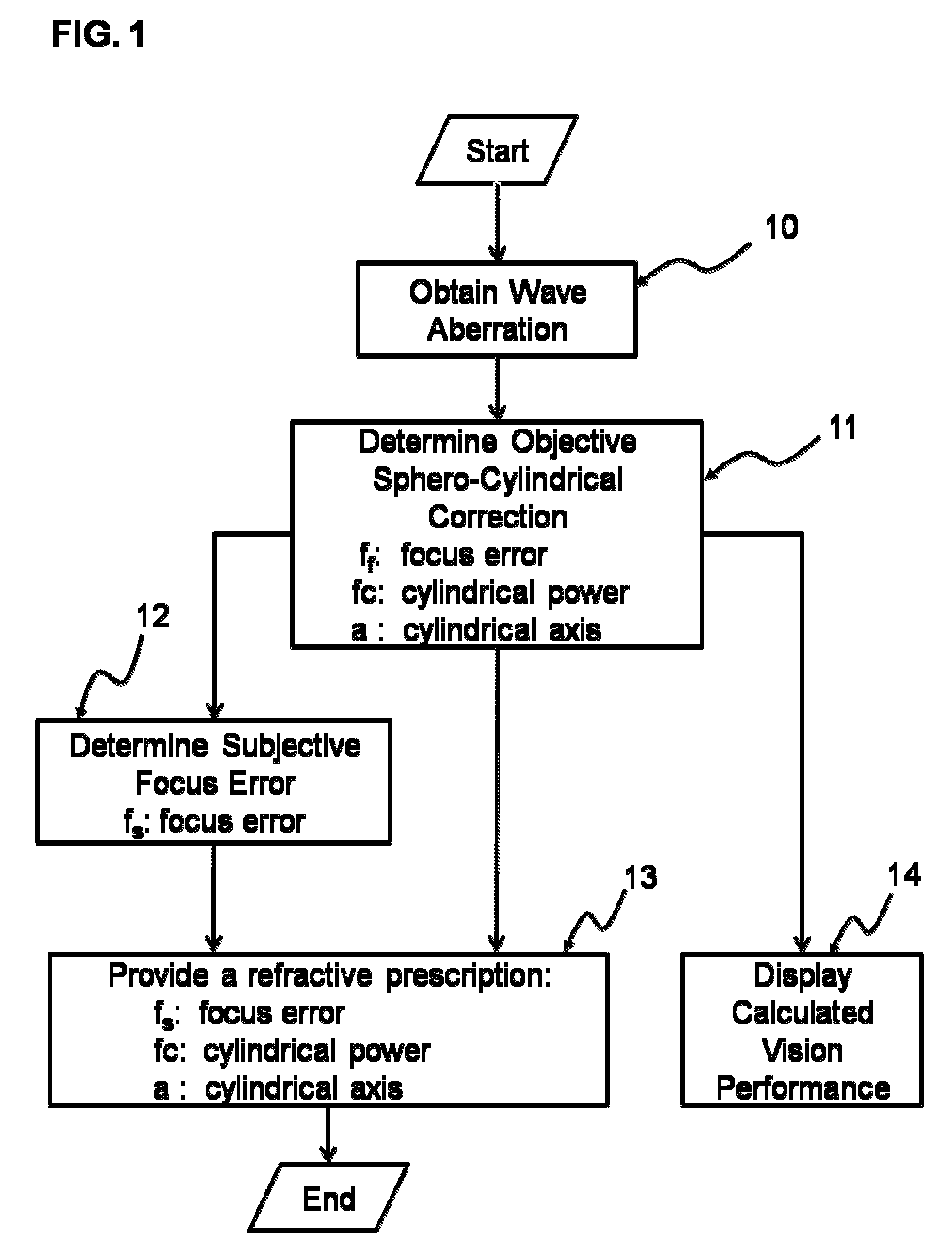
[0027]FIG. 1 shows a flow chart for an improved method for determining a refractive correction of an eye based on an objective measurement of the eye's wav...


PUM


Abstract

Methods and devices are provided to obtain refractive correction with superior visual acuity (e.g., 20 / 10) by achieving an astigmatism-free customized refractive correction. The astigmatism-free customized refractive correction involves obtaining an objective and precise measurement of cylindrical power in a resolution between 0.01 D and 0.10 D in an eye using an objective aberrometer, reliably relating the cylindrical axis obtained from the objective aberrometer to that in a phoroptor, determining an optimized focus error of an eye through subjective refraction with a phoroptor, generating a customized refraction by combining the objective measured cylindrical power, the objective measured cylindrical axis, and the subjectively measured focus power, fabricating a custom lens with a tolerance finer than 0.09 D based on the generated customized refraction, and delivering an ophthalmic lens that can provide an astigmatism-free refractive correction for an eye.

Description

CROSS-REFERENCES TO RELATED APPLICATIONS[0001]This application is a continuation of International Patent Application No. PCT / US2009 / 066148, filed Nov. 30, 2009, which claims priority to provisional U.S. patent application No. 61 / 200,494 titled “ Methods and processes for refractive correction of an eye” by Liang, filed Dec. 1, 2008, and provisional U.S. patent application No. 61 / 208,045 titled “Methods and devices for high-definition refractive correction of human eyes” by Liang, filed on Feb. 20, 2009, which are incorporated herein by reference.FIELD OF THE INVENTION[0002]The invention relates generally to refractive correction of eyes, and more specifically to the correction of myopia, hyperopia, and presbyopia.BACKGROUND OF THE INVENTION[0003]Refractive corrections for human eyes can be characterized into two general categories. The first category is the conventional method of vision correction which corrects for and the eye's focus error and cylindrical error as measured using a...

Claims


Application Information

Patent Timeline
Patent Type & Authority Patents(United States)
IPC IPC(8): A61B3/10
CPCG02C7/02A61B3/0025A61B3/103A61B3/0285A61B3/1015G02C7/022G02C2202/22A61B3/185G01M11/0228G02C7/027
Inventor LIANG, JUNZHONG
Owner PERFECT VISION TECH HK
Learn More