Pumping device having a pressure adjustable function

a technology of pumping device and function, which is applied in the direction of piston pump, positive displacement liquid engine, packaging goods type, etc., to achieve the effect of ensuring safe operation of the pumping device and being easily and conveniently operated

Active Publication Date: 2013-04-16
CRAFTS & CARRIERS TAIWAN
View PDF2 Cites 13 Cited by
  • Summary
  • Abstract
  • Description
  • Claims
  • Application Information

AI Technical Summary

Benefits of technology

[0007]According to the primary advantage of the present invention, when the air pressure in the receiving chamber of the barrel reaches a predetermined value, the pressure adjusting unit provides a pressure release function to partially release the air pressure in the receiving chamber of the barrel so as to ensure a safe operation of the pumping device.
[0008]According to another advantage of the present invention, the fluid is circulated in the receiving chamber of the barrel so that the pumping device is operated easily and conveniently.
[0009]Further benefits and advantages of the present invention will become apparent after a careful reading of the detailed description with appropriate reference to the accompanying drawings.BRIEF DESCRIPTION OF THE SEVERAL VIEWS OF THE DRAWING(S)
[0010]FIG. 1 is a top view of a pumping device in accordance with the preferred embodiment of the present invention.
[0011]FIG. 2 is a cross-sectional view of the pumping device taken along line 2-2 as shown in FIG. 1.
[0012]FIG. 3 is a schematic operational view of the pumping device as shown in FIG. 2 in use.

Problems solved by technology

However, a user can directly control the operation unit to operate the pumping device so that the pumping device does not have a security mechanism limit the operation unit so as to prevent the user from operating the pumping device improperly.

Method used


Image

  • Pumping device having a pressure adjustable function
  • Pumping device having a pressure adjustable function
  • Pumping device having a pressure adjustable function

Examples


Embodiment Construction

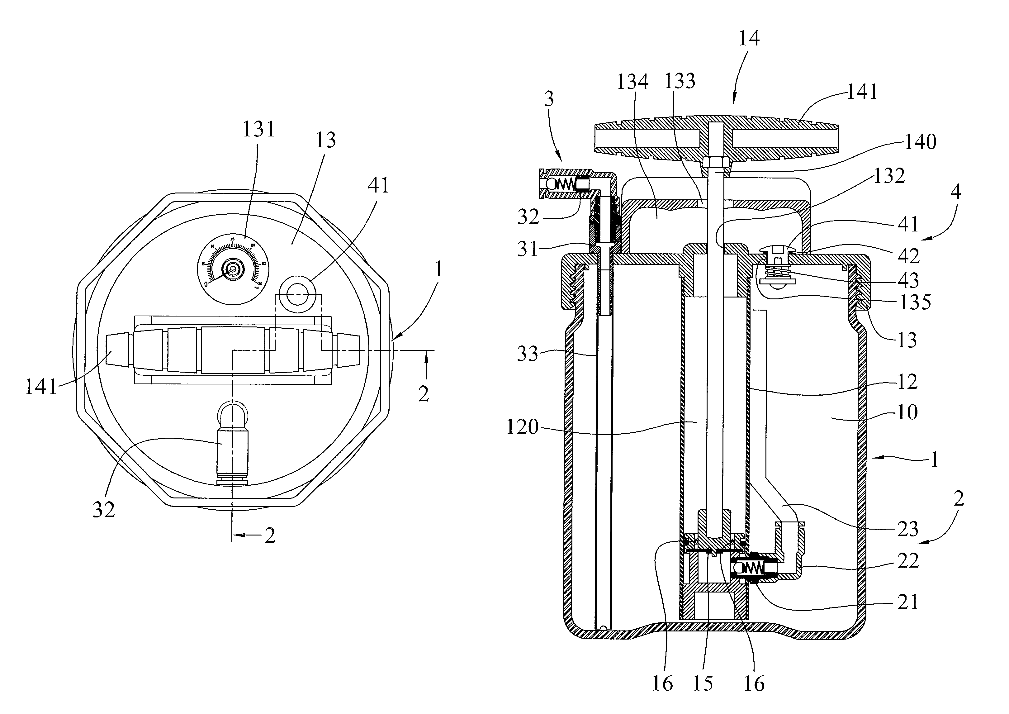
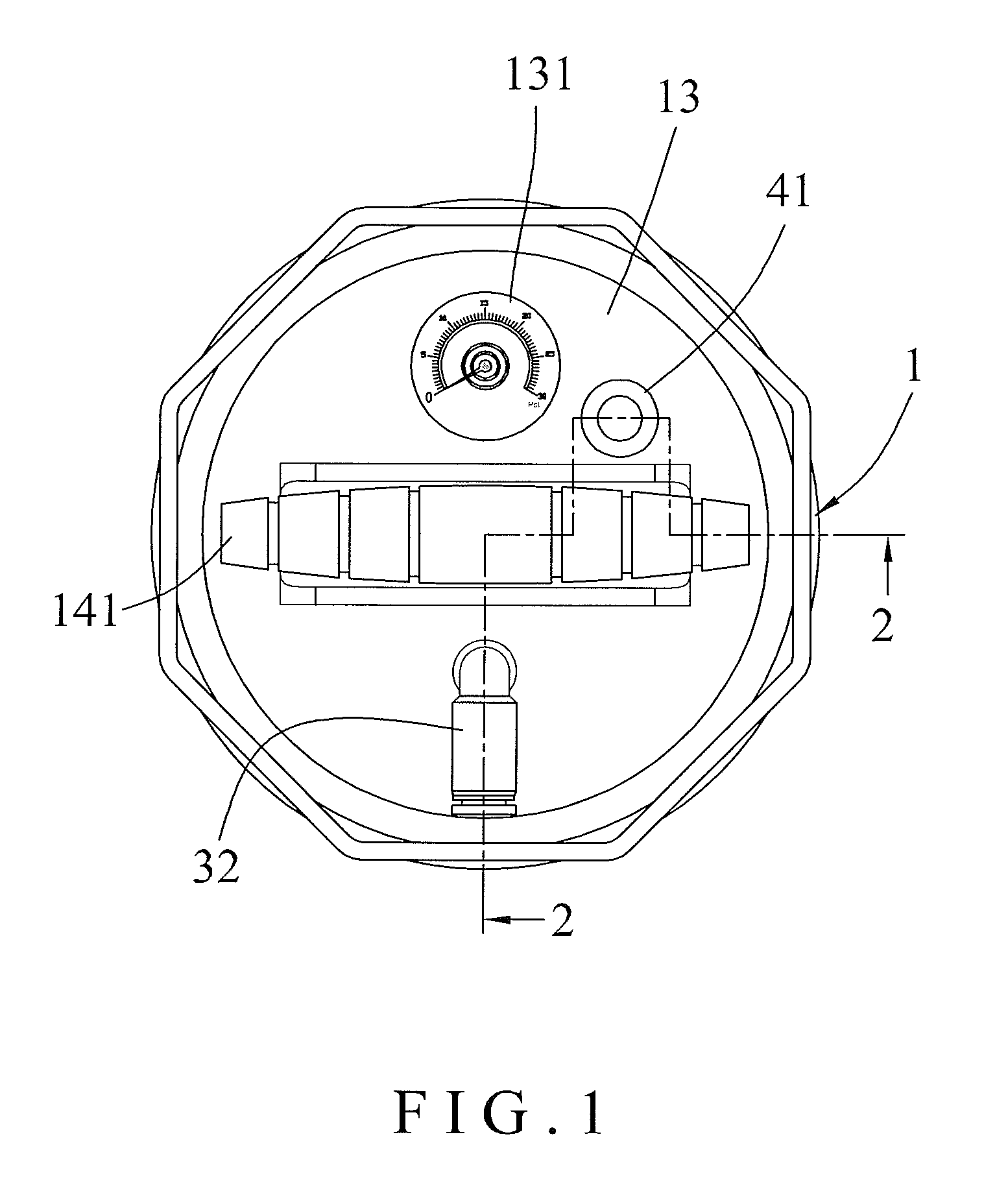
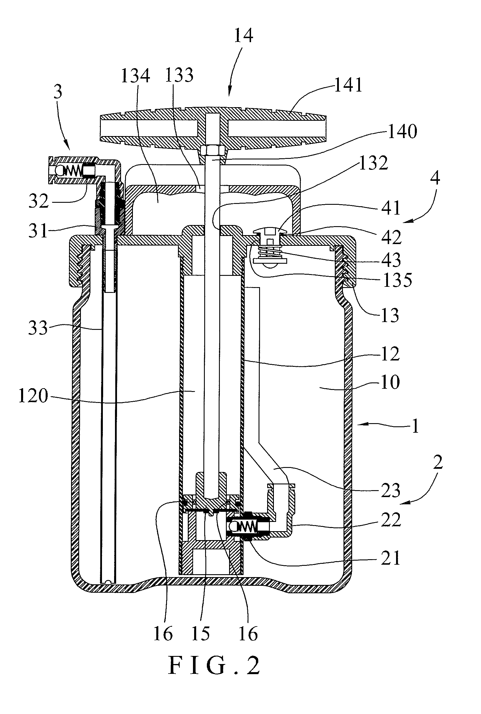
[0015]Referring to the drawings and initially to FIGS. 1 and 2, a pumping device in accordance with the preferred embodiment of the present invention comprises a barrel 1, a top cover 13 mounted on an open top of the barrel 1 and connected to an ambient environment, a cylinder 12 mounted in the barrel 1 and connected to the top cover 13, a piston 15 movably mounted in the cylinder 12, a plurality of check valves 16 mounted on the piston 15 to move in concert with the piston 15, an operation unit 14 mounted on the top cover 13 and connected with the piston 15 to move the piston 15 relative to the cylinder 12, a connecting unit 2 mounted in the barrel 1 and connected between the barrel 1 and the cylinder 12, a pressure adjusting unit 4 connected between the barrel 1 and the top cover 13, and a delivery unit 3 mounted on the top cover 13 and connected to the barrel 1.

[0016]The barrel 1 has an inner portion provided with a receiving chamber 10 to receive the cylinder 12, the connecting ...


PUM

PropertyMeasurementUnit
pressureaaaaaaaaaa
air pressureaaaaaaaaaa

Abstract

A pumping device includes a barrel, a top cover mounted on an open top of the barrel, a cylinder mounted in the barrel and connected to the top cover, a piston movably mounted in the cylinder, a plurality of check valves mounted on the piston, an operation unit mounted on the top cover and connected with the piston, a connecting unit mounted in the barrel and connected between the barrel and the cylinder, and a pressure adjusting unit connected between the barrel and the top cover. Thus, when the air pressure in the receiving chamber of the barrel reaches a predetermined value, the pressure adjusting unit provides a pressure release function to partially release the air pressure in the receiving chamber of the barrel so as to ensure a safe operation of the pumping device.

Description

BACKGROUND OF THE INVENTION[0001]1. Field of the Invention[0002]The present invention relates to a pumping device and, more particularly, to a pumping device for pumping a fluid, such as a gas, liquid and the like.[0003]2. Description of the Related Art[0004]A conventional pumping device comprises a barrel, a top cover mounted on the top of the barrel, a cylinder mounted in the barrel, a piston movably mounted in the cylinder, and an operation unit mounted on the top cover and connected with the piston to move the piston relative to the cylinder. Thus, the piston is driven by the operation unit to pump a fluid into the cylinder and the barrel. However, a user can directly control the operation unit to operate the pumping device so that the pumping device does not have a security mechanism limit the operation unit so as to prevent the user from operating the pumping device improperly.BRIEF SUMMARY OF THE INVENTION[0005]In accordance with the present invention, there is provided a pum...

Claims


Application Information

Patent Timeline
Patent Type & Authority Patents(United States)
IPC IPC(8): F04F1/06F04B9/14F04B53/12B65B1/16B65D83/00
CPCF04B9/14F04B17/06F04B23/023F04B33/00F04B35/06F04B49/022
Inventor HSU, MEI-CHIN
Owner CRAFTS & CARRIERS TAIWAN
Why Eureka
Try Eureka