LED light bulb equipped with light transparent shell fastening structure

a technology of light-transparent shell and led light bulb, which is applied in the direction of discharge tube main electrodes, semiconductor devices of light sources, light and heating apparatus, etc., can solve the problems of inability to meet the severe high temperature test of materials, inability to provide strong adhesion force and great heat-resistance, etc., to achieve easy loosening or separation

Inactive Publication Date: 2013-04-16
CHUANG SHENG YI
View PDF16 Cites 82 Cited by
  • Summary
  • Abstract
  • Description
  • Claims
  • Application Information

AI Technical Summary

Benefits of technology

[0007]In view of elements in the conventional LED light bulb could easily loosen off or separate due to simple coupling via adhesive during high temperature test in the severe safety regulation tests, the present invention aims to provide a fastening structure for LED light bulbs to substitute the conventional bonding techniques by using adhesive to ensure that the LED light bulbs can be maintained intact for long duration in the high temperature test without aging or separation.
[0009]Moreover, the LED light bulb further includes a coupling holder in the housing chamber. The coupling holder has a fastening portion at one end fastening to the power receiving base and is divided by an insulation wall to form a circuit holding compartment to hold the power conversion board, and also has a longitudinal holder retaining portion. The heat sink has a third holding portion corresponding and fastening to the longitudinal holder retaining portion to restrict the coupling holder and heat sink from moving vertically against each other. The coupling holder further has at least one transverse holder retaining portion, and the heat sink has at least one fourth holding portion corresponding and fastening to the transverse holder retaining portion to restrict the assembly holder and heat sink from turning against each other.
[0010]By means of the construction set forth above, the light transparent shell can be firmly fastened to the heat sink through the longitudinal shell retaining portion and transverse shell retaining portion on the outer wall. As the light transparent shell has the positioning structure formed on the outer wall, it can be made of plastics with a larger curved surface formed. Take a virtual sphere for an example, the curved surface of the light transparent shell can cover at least 75% of the virtual spherical surface, thus a wider light transparent range can be achieved to increase illumination.

Problems solved by technology

Although there are various types of the adhesive, those with better heat-resistant capability usually have weaker adhesion force, while those with stronger adhesion force often are deficient in heat-resistance.
Thus most adhesive cannot provide both strong adhesion force and great heat-resistant capability.
Moreover, it is a severe test for most adhesive to be tested in the environment with temperature variations from 90° C. to −25° C. for dozens of days while the tersional force is constantly applied to.
While this prior art has listed many possible embodiments for materials of the foam, it is not sure whether those materials can pass the severe high temperature test.
Since the glass lamp shade has a smoother edge, it is afraid that using the adhesive to bond the glass lamp shade to the lamp base or heat sink is difficult to pass the high temperature test.
However, although using multi-layer or multi-material adhesive to hold the lamp shade might increase the chance to pass the safety regulation tests, the production cost also increases.

Method used


Image

  • LED light bulb equipped with light transparent shell fastening structure
  • LED light bulb equipped with light transparent shell fastening structure
  • LED light bulb equipped with light transparent shell fastening structure

Examples


Embodiment Construction

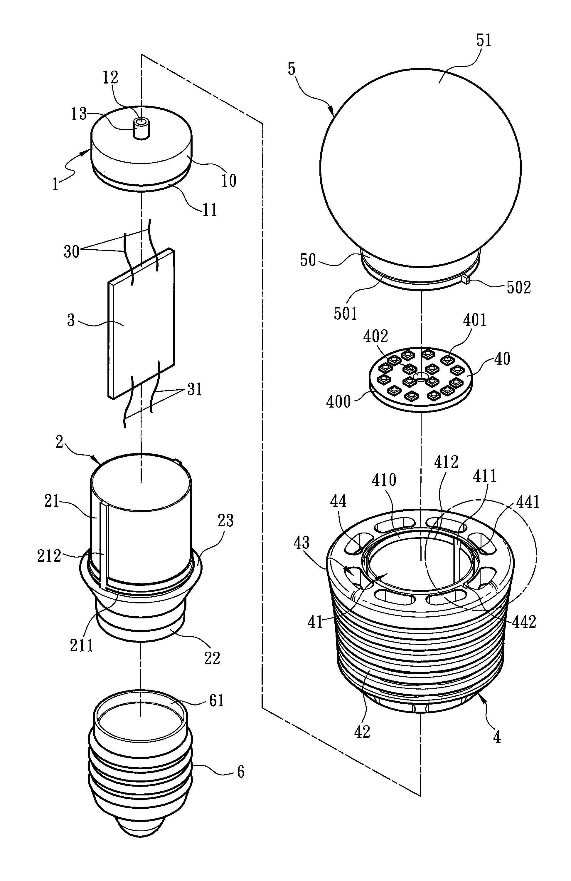
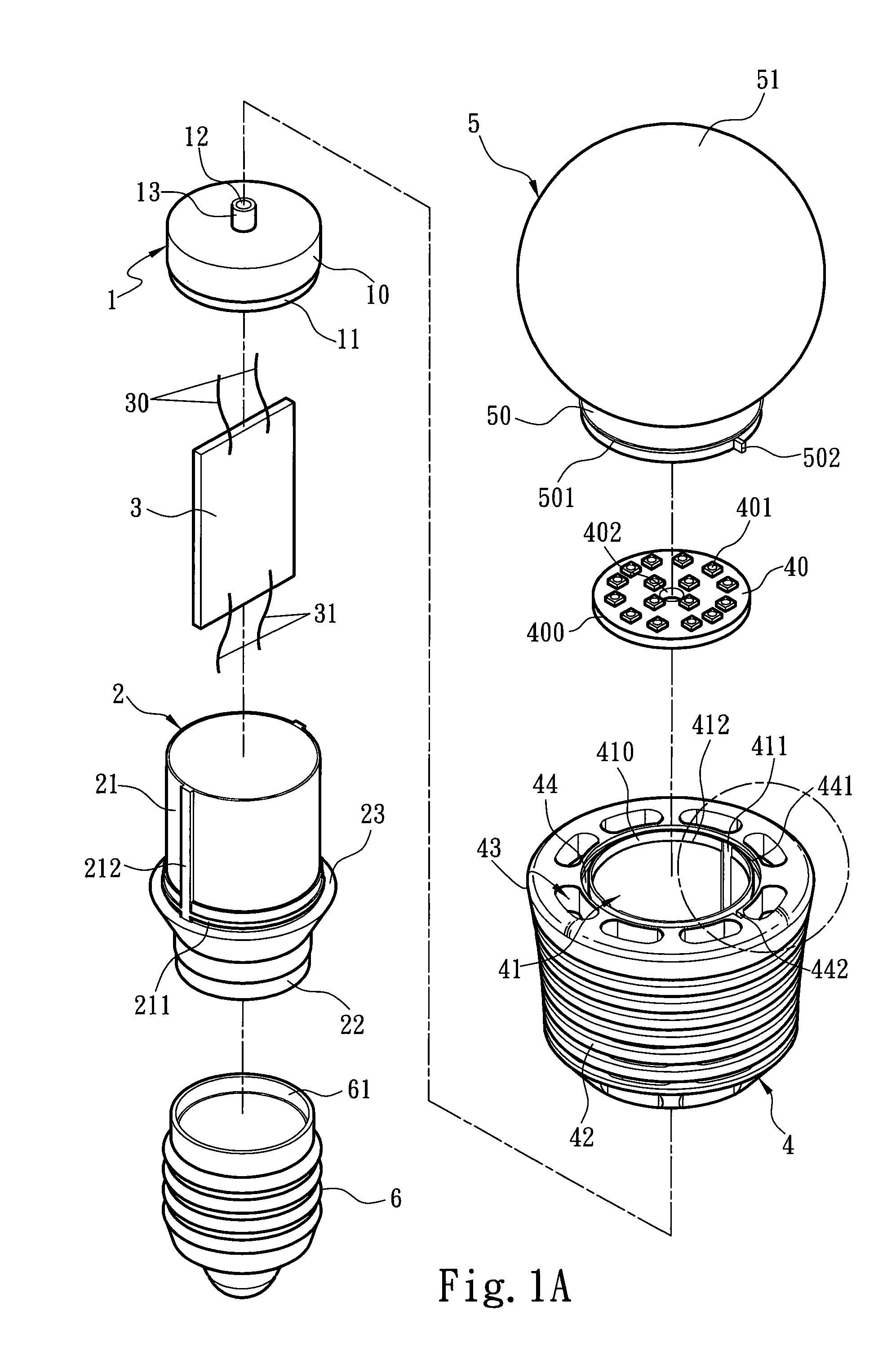
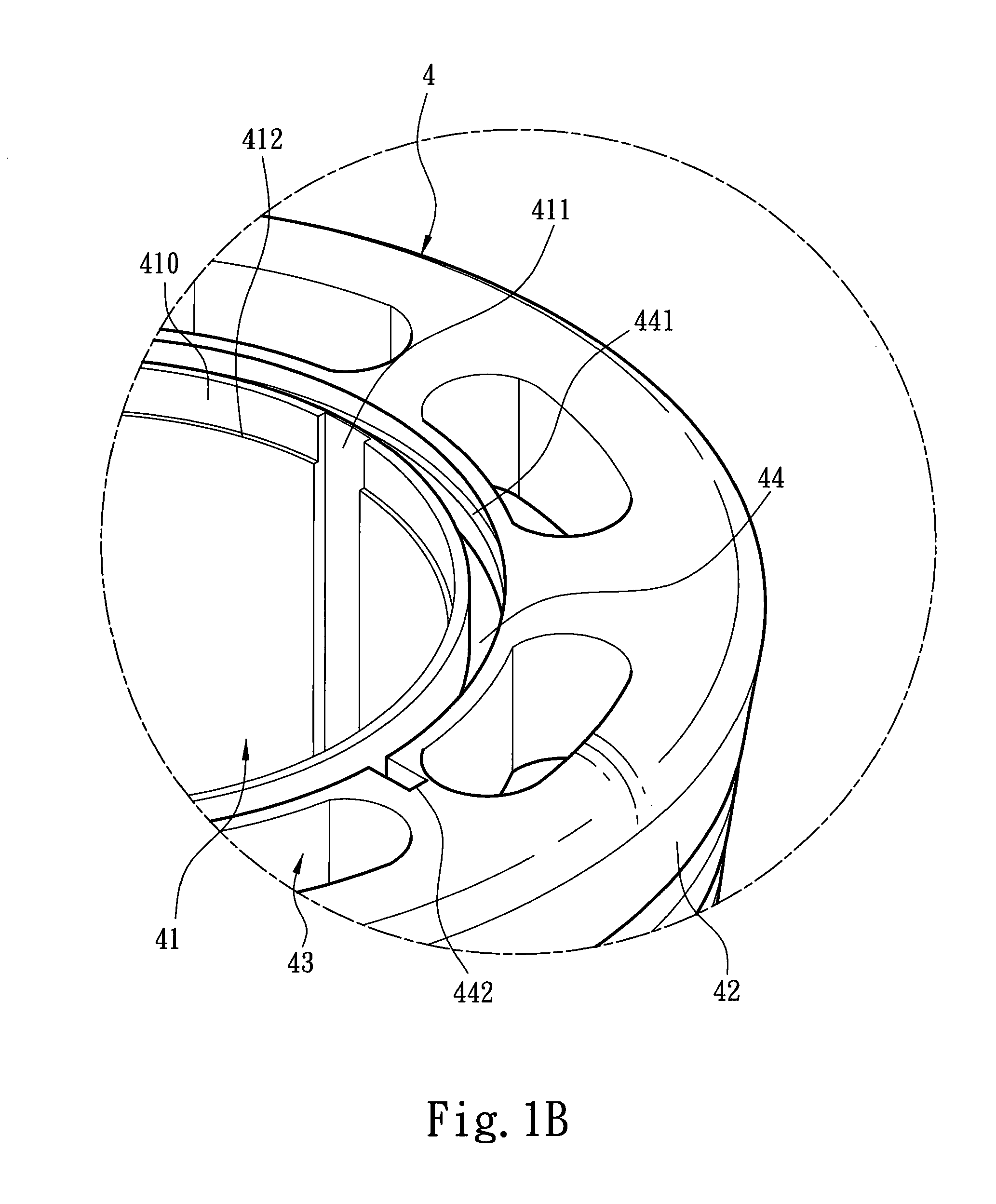
[0019]The present invention aims to provide an LED light bulb equipped with light transparent shell fastening structure. Please refer to FIGS. 1A through 4 for a first embodiment of the invention. The LED light bulb in this embodiment includes a light transparent shell 5, a power receiving base 6, a heat sink 4 and a coupling holder 2 located between the light transparent shell 5 and power receiving base 6, at least one light source baseboard 40 located in the light transparent shell 5 and a power conversion board 3 electrically connected to the light source baseboard 40 and power receiving base 6. The power conversion board 3 is preferably a switch-type power circuit. The heat sink 4 has a housing chamber 41 to hold the power conversion board 3. The light source baseboard 40 holds a plurality of LEDs 401 located thereon, and can be an aluminum baseboard containing a plurality of conductive wires. Based on present techniques, the aluminum baseboard can be formed by stacking a copper...


PUM


Abstract

An LED light bulb includes a power conversion board, at least one light source baseboard electrically connected to the power conversion board, a heat sink and a light transparent shell to hold the light source baseboard. The heat sink has a wedged groove with a first holding portion formed thereon. The light transparent shell includes a sphere and a neck wedged in the wedged groove. The sphere and neck have an inner wall surrounded to hold the power conversion board and an outer wall opposite to the inner wall. The neck has a longitudinal shell retaining portion on the outer wall corresponding and fastening to the first holding portion and at least one transverse shell retaining portion. The wedged groove has at least one second holding portion corresponding and fastening to the transverse shell retaining portion to restrict relative turning of the light transparent shell and heat sink.

Description

[0001]This application is a continuation-in-part, and claims priority, of from U.S. patent application Ser. No. 13 / 012,581 filed on Jan. 24, 2011, entitled “INSULATION REINFORCING LIGHT BULB”, the entire contents of which are hereby incorporated by reference.FIELD OF THE INVENTION[0002]The present invention relates to an LED light bulb equipped with light transparent shell fastening structure and particularly to an improved fastening structure to couple a light transparent shell with a heat sink.BACKGROUND OF THE INVENTION[0003]Light emitting diode (LED) provides many advantages such as longer lifespan, less power consumption, higher illumination and more eco-friendly materials. With advance of LED fabrication process and lower cost thereof, LED is not only adopted on traffic lights or indication lights of electric appliances, it also can be used on environmental decoration or lighting fixtures. As application scope of the LED lamps has been greatly expanded, they have to pass vario...

Claims


Application Information

Patent Timeline
Patent Type & Authority Patents(United States)
IPC IPC(8): F21V29/00H01J7/24
CPCF21K9/135F21V29/83F21V3/00F21Y2105/001F21V17/005F21Y2101/02F21V23/002F21Y2105/10F21K9/232F21Y2115/10
Inventor CHUANG, SHENG-YI
Owner CHUANG SHENG YI
Why Eureka
Try Eureka