Apparatus for driving light emitting device using pulse-width modulation

a technology of pulse width and light emitting device, which is applied in the direction of electrical apparatus, light sources, instruments, etc., can solve the problems of large the limitation of embedding a multi-channel led driver circuit into the driving circuit, and the heat generation in the driving control elements. , to achieve the effect of improving the interchannel current matching characteristic and reducing heat generation in the driving control elements

Active Publication Date: 2013-04-16
SKAICHIPS CO LTD
View PDF7 Cites 10 Cited by
  • Summary
  • Abstract
  • Description
  • Claims
  • Application Information

AI Technical Summary

Benefits of technology

[0012]An aspect of the present invention provides an apparatus for driving an LED, which is capable of reducing heat generation in driving control elements, regardless of an LED forward voltage deviation between channels, and improving an interchannel current matching characteristic by operating driving control transistors, which are installed in each channel in order to control the driving of a multi-channel LED, in a PWM scheme.

Problems solved by technology

The linear scheme is advantageous in terms of price, but is problematic in terms of heat generation in a driver IC due to an LED forward voltage (VF) deviation between channels.
Thus, there is a limitation in embedding a multi-channel LED driver circuit into an IC.
However, in the conventional multi-channel LED driver circuit, the forward voltage deviation exists between the LED strings, and a high voltage is applied to LED driving control elements (transistors) by the forward voltage deviation.
Thus, a great deal of heat is generated in the driving control elements.
Due to the heat generation in the driving control elements, there is a limitation in embedding multi-channels into the IC.
There is a need a compensation circuit for solving those problems, which will increase the price of the device.

Method used


Image

  • Apparatus for driving light emitting device using pulse-width modulation
  • Apparatus for driving light emitting device using pulse-width modulation
  • Apparatus for driving light emitting device using pulse-width modulation

Examples


Embodiment Construction

[0034]Exemplary embodiments of the present invention will now be described in detail with reference to the accompanying drawings. The invention may, however, be embodied in many different forms and should not be construed as being limited to the embodiments set forth herein. Rather, these embodiments are provided so that this disclosure will be thorough and complete, and will fully convey the scope of the invention to those skilled in the art. In the drawings, the thicknesses of layers and regions are exaggerated for clarity. Like reference numerals in the drawings denote like elements, and thus their description will be omitted.

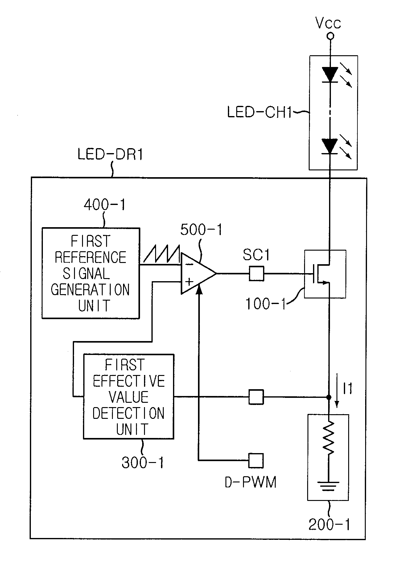
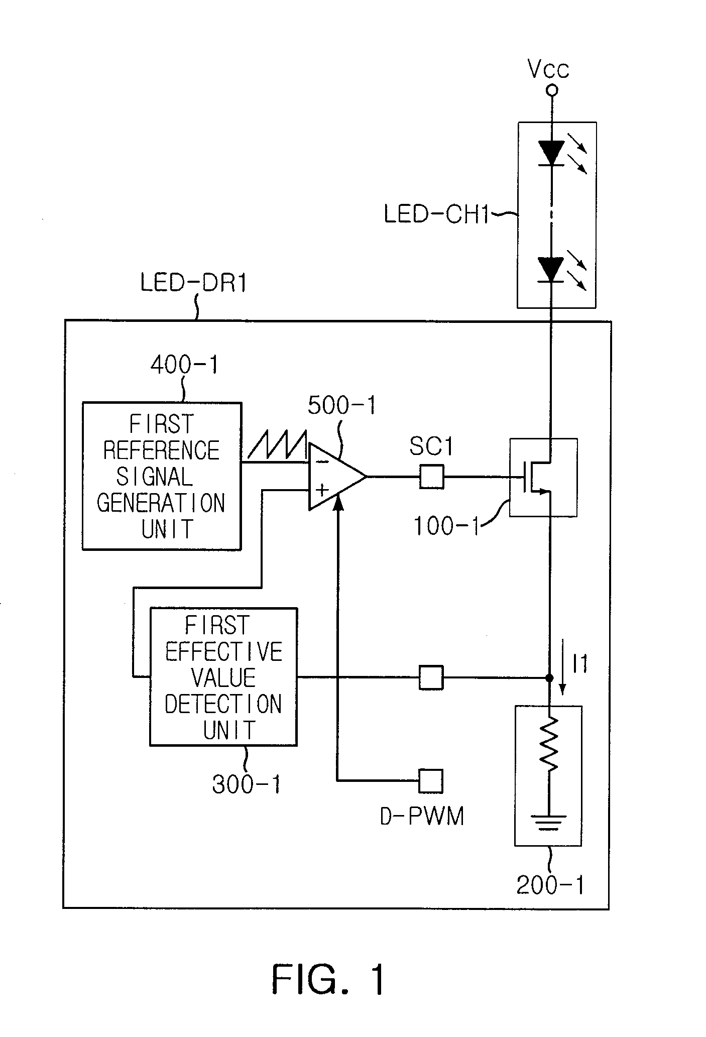
[0035]FIG. 1 is a block diagram of an apparatus for driving alight emitting device (LED) according to an embodiment of the present invention. Referring to FIG. 1, an apparatus for driving an LED according to an embodiment of the present invention a first driving control element 100-1, a first current detection unit 200-1, a first effective value detection un...


PUM


Abstract

An apparatus for driving a light emitting device (LED) is provided. The apparatus for driving the LED includes a first driving control element, a first current detection unit, a first effective value detection unit, a first reference signal generation unit, and a first comparison unit. The first driving control element controls a current flowing through a first LED channel, in response to a first pulse-width modulated control signal. The first current detection unit detects the current flowing through the first LED channel. The first effective value detection unit detects an effective value of the current detected by the first current detection unit. The first reference signal generation unit generates a preset reference signal having a sawtooth waveform. The first comparison unit compares the reference signal from the first reference signal generation unit with the effective value from the first effective value detection unit.

Description

CROSS-REFERENCE TO RELATED APPLICATIONS[0001]This application claims the priority of Korean Patent Application No. 10-2009-0125656 filed on Dec. 16, 2009, in the Korean Intellectual Property Office, the disclosure of which is incorporated herein by reference.BACKGROUND OF THE INVENTION[0002]1. Field of the Invention[0003]The present invention relates to an apparatus for driving a light emitting device, which is applicable to an illumination device or a backlight unit (BLU), and more particularly, to an apparatus for driving a light emitting device using a pulse-width modulation (PWM), in which a driving control transistor provided in each channel in order to control the driving of a multi-channel light emitting device operates in a PWM scheme.[0004]2. Description of the Related Art[0005]Light emitting devices (LEDs) have been applied in various fields, for example, illumination devices or backlight units, and their applications are currently being expanded.[0006]In such LED backligh...

Claims


Application Information

Patent Timeline
Patent Type & Authority Patents(United States)
IPC IPC(8): H05B39/02
CPCH05B33/0818H05B33/0827H05B45/46H05B45/37
Inventor KONG, SEUNG KONLEE, JAE SHINKIM, JUNG HYUNKWON, JUNG SUNHWANG, BO HYUN
Owner SKAICHIPS CO LTD
Why Eureka
Try Eureka