Computed tomography apparatus for geological resource core analysis

a tomography and core analysis technology, applied in the direction of material analysis using wave/particle radiation, instruments, nuclear engineering, etc., can solve the problems affecting the accuracy of the analysis, and reducing the repair cost. , the effect of reducing the repair cos

Active Publication Date: 2013-04-16
KOREA INST OF GEOSCI & MINERAL RESOURCES
View PDF13 Cites 11 Cited by
  • Summary
  • Abstract
  • Description
  • Claims
  • Application Information

AI Technical Summary

Benefits of technology

[0062]According to the computed tomography apparatus for geological resource core analysis, there are effects in that it can conveniently utilize a computed tomography apparatus for industrial use and the movement between the CT beam transmitter and the detector is decreased, thereby performing the accurate measurement thereof.
[0063]Also, there is another effect in that the computed tomography apparatus is not frequently out of work, thereby reducing the repair cost.
[0064]According to the present invention, the cylinder type sample having a very long major axis can be scanned through the computed tomography apparatus without meeting any obstruction and the sample can be restored in three dimensions. Also, when the CT beam transmission part, the sample locate at the rotation axis, and the X-ray detector are appropriately and spatially arranged according to the geometric magnification required, if the cylinder type sample has a very long major axis, only a part of the sample can be created as an image through the detector. At this time, firstly, the part of the sample is scanned and then, the rest of the sample is scanned by moving the CT beam transmission part and the detector upwardly or downwardly, thereby solving the corresponding problem. Moreover, as though the cylinder type sample has a very long major axis, the CT scan is repeated a several times and the results are accumulated, thereby solving the problem.
[0065]Also, the sample of a big size can be comfortably scanned and the CT scan having the resolution of a micrometer scale can be performed in case of the sample of a suitable size.
[0066]Moreover, since the sample rotating device and the supporting members having the X-ray detector can be moved horizontally, the distance between the CT beam transmission part and the detector and the distance between the sample and the detector can be automatically adjusted respectively, so that the distance between the CT beam transmission part and the detector is minimized and the distance between the sample and the detector is maximized, thereby obtaining the maximum geometric magnification.
[0067]Moreover, a pressure core sample of a gas hydrate type, which is very difficult test subject in the field of the geological resource, can be safely scanned.

Problems solved by technology

Accordingly, the cost of constructing the hardware for satisfying these requirements is considerable.
In this case, as described above, the resolution thereof can be deteriorated owing to the vibration phenomenon of the gantry.
Since the shape of the drilling core is a cylinder, where the X-ray scan is simply performed with the object of viewing the interior structure thereof, it is not easy to grasp the physical properties inside the core owing to very different X-ray transmission images between the middle and edge portions thereof.
However, in case of collecting the sample in addition, it is time-consuming.
Also, in case of any core sample obtained from soft stratum, it is not easy to collect the piece type sample itself.
However, the optimization CT on the sample core of the cylinder shape is not yet developed.
That is, it remains an unsolved problem.
In other word, since the cylinder type sample has a very long major axis, it cannot smoothly perform the experiment required in the field of the geological resource by using the CT beam transmission part and the X-ray detector and by means of the arranging and operating manners of the rotation axis used in the existed industrial CT.
However, the core sample requires more sufficient X-ray san than that of the medical CT.
Accordingly, it cannot also, smoothly perform the experiment required in the field of the geological resource.
However, in this case, since the entire space thereof is restricted by the size of the cabinet, the size of the analyzing sample is restricted without question.
Also, as though the gas hydrate is contained in the metal container, where the gas hydrate is completely dissociated, it can explode.
However, it is very difficult for the existed cabinet type shielding CT to meet this condition.
If a refrigerator is installed in the inside of the small cabinet type shielding membrane, since the vibration generated by the operation of the refrigerator is directly transmitted to the CT parts, it is hard to obtain the high resolution material.
Accordingly, the manufacturing cost thereof becomes more expensive.
Since the CT beam transmission part and the detector are rotated or moved left and right, it is frequently out of work, thereby increasing the maintenance cost.
Also, since the operations of rotating or horizontally moving the CT beam transmitter and the detector are large, it is out of focus, thereby it has difficulty in performing the accurate measurement.
Accordingly, it has considerable difficulty for using as the industrial CT, besides the medical CT.
An improvement thereof has been remained a big issue in the art.

Method used


Image

  • Computed tomography apparatus for geological resource core analysis
  • Computed tomography apparatus for geological resource core analysis
  • Computed tomography apparatus for geological resource core analysis

Examples


Embodiment Construction

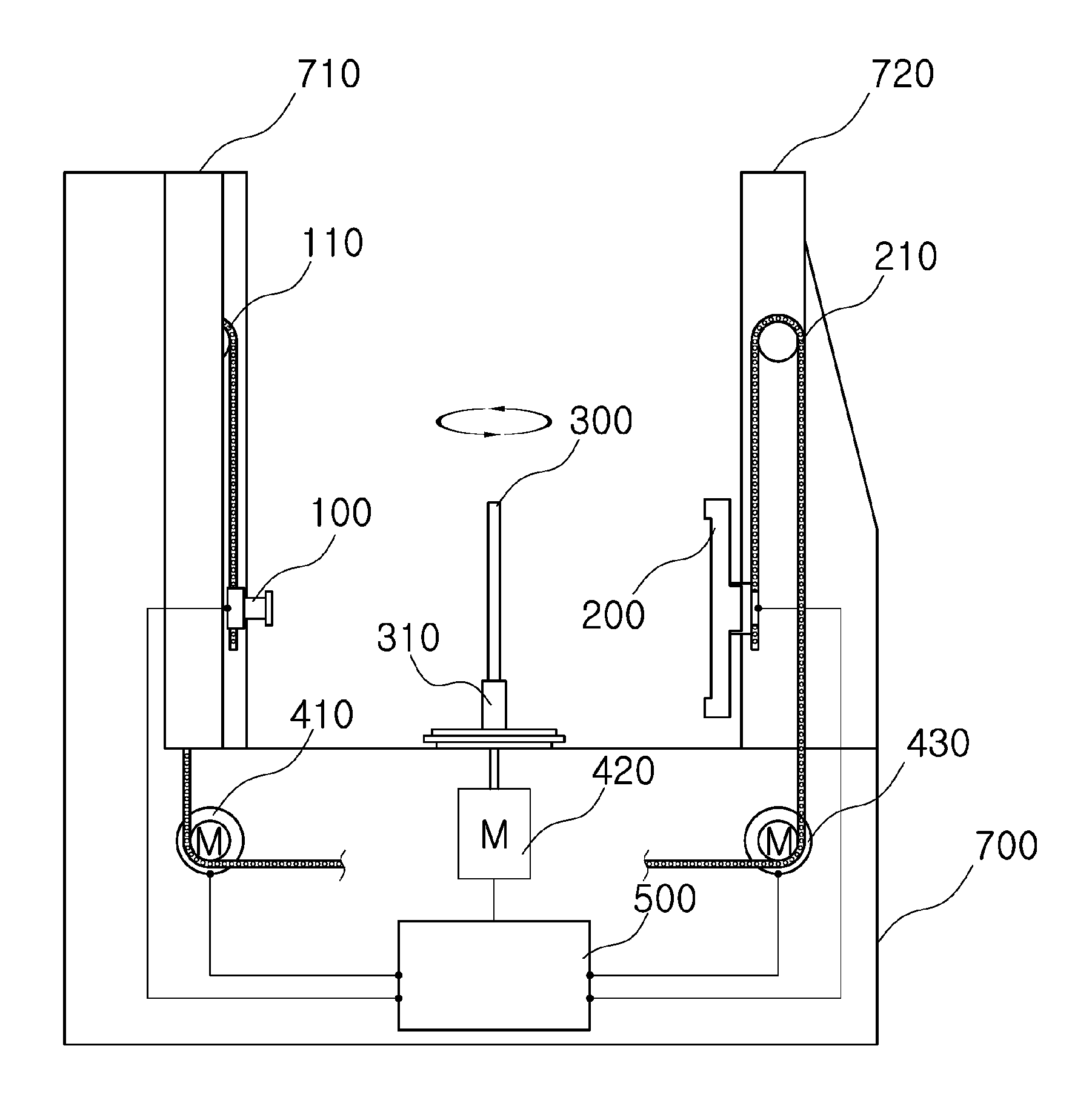
[0092]In accordance with the present invention to achieve the object thereof, there is provided a computed tomography apparatus for geological resource core analysis including:

[0093]a main body 700 having a CT beam transmission part 100, a detector 200, and a sample rotating device 310;

[0094]the CT beam transmission part 100 installed and constructed in a first supporting member 710 installed in one side of the main body, connected to a CT beam transmission part moving member 110, moved up and down when the CT beam transmission part moving member is moved up and down, and transmitting a CT beam;

[0095]the detector 200 installed and constructed in a second supporting member 720 installed in the other side of the main body, connected to a detector moving member 210, moved up and down though the detector moving member 210, and acquiring the CT beam transmitted through the CT beam transmission part 100; and

[0096]the sample rotating device 310 installed and constructed between the CT beam...


PUM

PropertyMeasurementUnit
angleaaaaaaaaaa
angleaaaaaaaaaa
computed tomographyaaaaaaaaaa

Abstract

A computed tomography apparatus for geological resource core analysis, more particularly to a computed tomography apparatus for geological resource core analysis in that it can conveniently utilize a computed tomography apparatus for industrial use, the movement between the CT beam transmitter and the detector is decreased, thereby performing an accurate measurement and breaking down infrequently, and especially, it can easily perform a CT scan on a cylinder type (or rod shape) sample having a very long major axis such as a geological resource core sample.

Description

TECHNICAL FIELD[0001]The present invention relates to a computed tomography apparatus for geological resource core analysis, more particularly to a computed tomography apparatus for geological resource core analysis in that it can conveniently utilize a computed tomography apparatus for industrial use, the movement between the CT beam transmitter and the detector is decreased, thereby performing an accurate measurement and breaking down infrequently, and especially, it can easily perform a CT scan on a cylinder type (rod shape) sample having a very long major axis such as a geological resource core sample.BACKGROUND ART[0002]In general, a computer tomography apparatus (CT) for medical purposes has a construction shown in FIG. 1. The best feature of the CT for medical purpose is a circular ring called as a gantry 15. In the frame of the ring thereof, the CT beam transmission part 10 and the X-ray detector 20 are opposed to each other.[0003]At this time, in the X-ray detector 20, the ...

Claims


Application Information

Patent Timeline
Patent Type & Authority Patents(United States)
IPC IPC(8): G01N23/04
CPCG01N23/046G01N2223/612G01N2223/419
Inventor JIN, JAE HWAKIM, JUN HOKIM, MIN JUNKIM, HAN SEOKPARK, CHIN KUNJIN, YOUNG DUCKYOON, MYOUNG HUN
Owner KOREA INST OF GEOSCI & MINERAL RESOURCES
Why Eureka
Try Eureka