Device and method for monitoring consumer test compliance
a consumer and test technology, applied in liquid transfer devices, instruments, transportation and packaging, etc., can solve the problems of inability to report the aspects of behavior, both kinds of methodologies have drawbacks, and verbal reports are not always appropriate for studying habits
- Summary
- Abstract
- Description
- Claims
- Application Information
AI Technical Summary
Benefits of technology
Problems solved by technology
Method used
Image
Examples
first embodiment
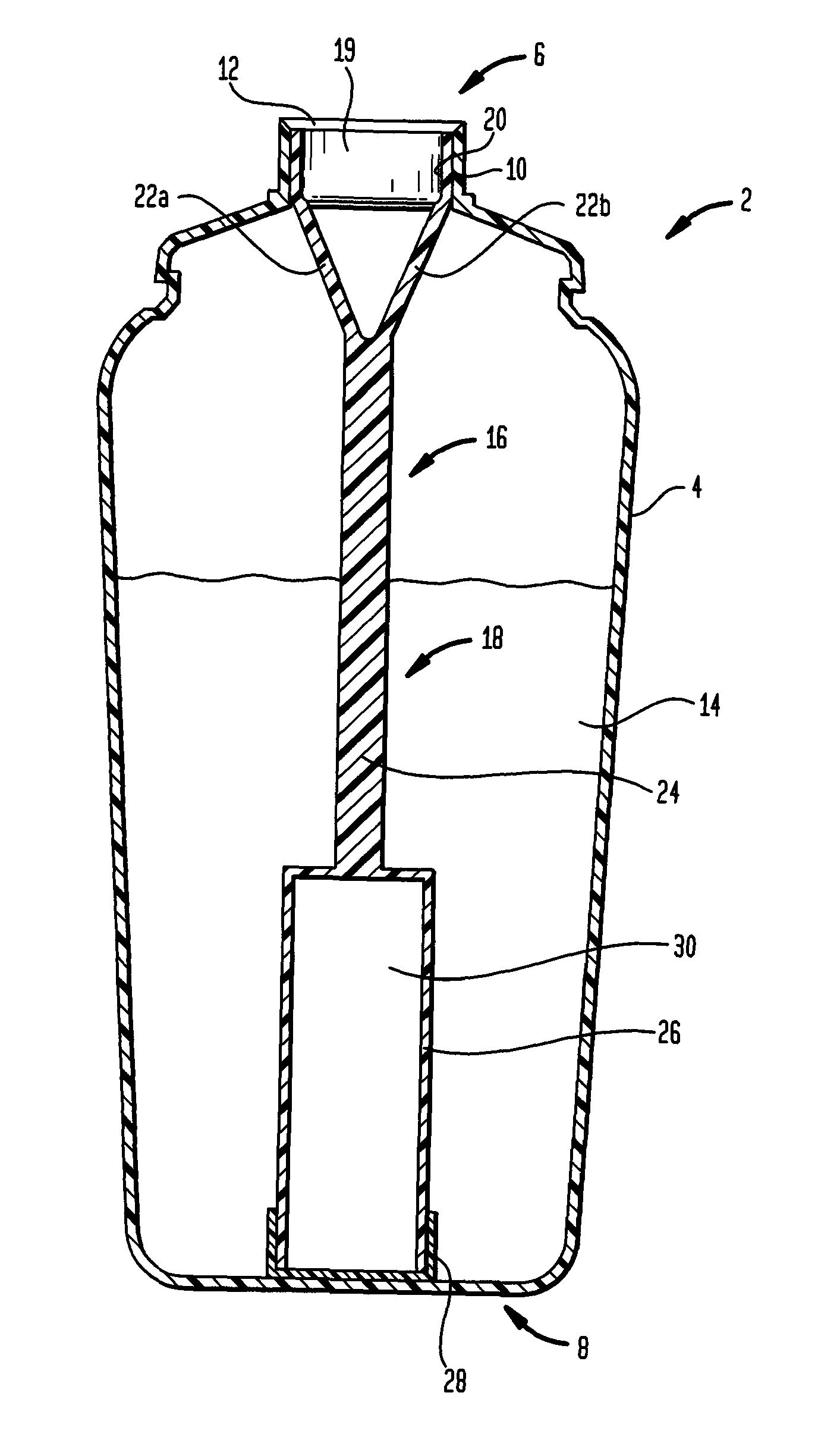
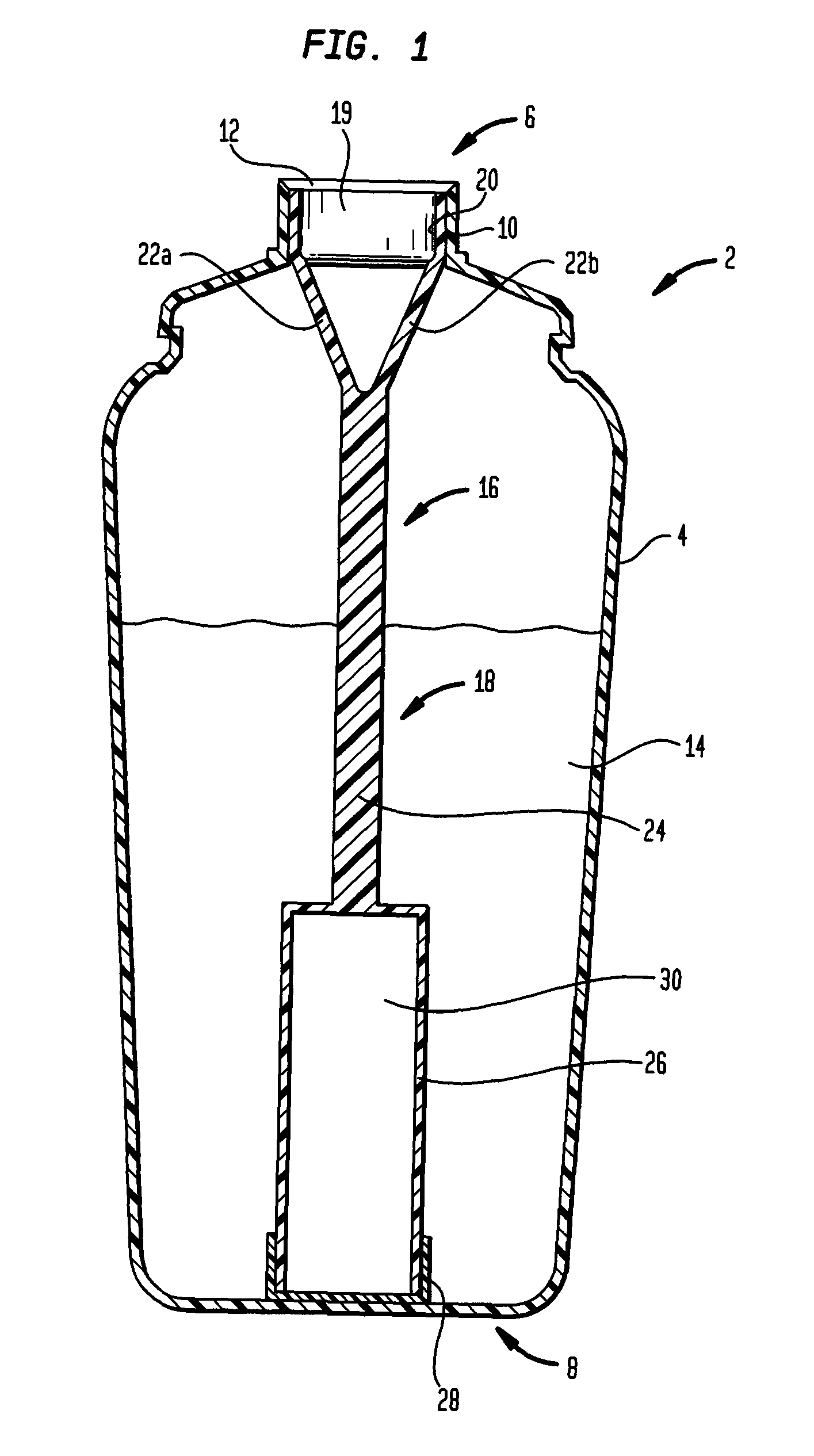
[0034]FIG. 1 illustrates the present invention. A bottle 2 is shown in cross-section. It is formed with a container body 4 having an open end 6 and a closed end 8. A neck 10 with a mouth 12 at a terminus of the neck is located at the open end. A flowable material 14 is held within the container body. A monitoring unit 16 is at least partially immersed within the flowable material.
[0035]The monitoring unit has a support rod 18 contacting and being supported by neck 10.
[0036]The rod is formed with a nesting ring 20 having an outer wall supportably nestable against an inner wall of the neck and an aperture 19 allowing transfer of flowable material out of the container body.
[0037]A pair of arms 22a, 22b connect opposite sections of the nesting ring to a central bar 24.
[0038]On a terminus of the central bar opposite that of the arms is a retention cage 26 having a hollow central area and sealed with a cap 28. Within the retention cage is a logger 30 sufficiently sealed by cap 28 to preve...
second embodiment
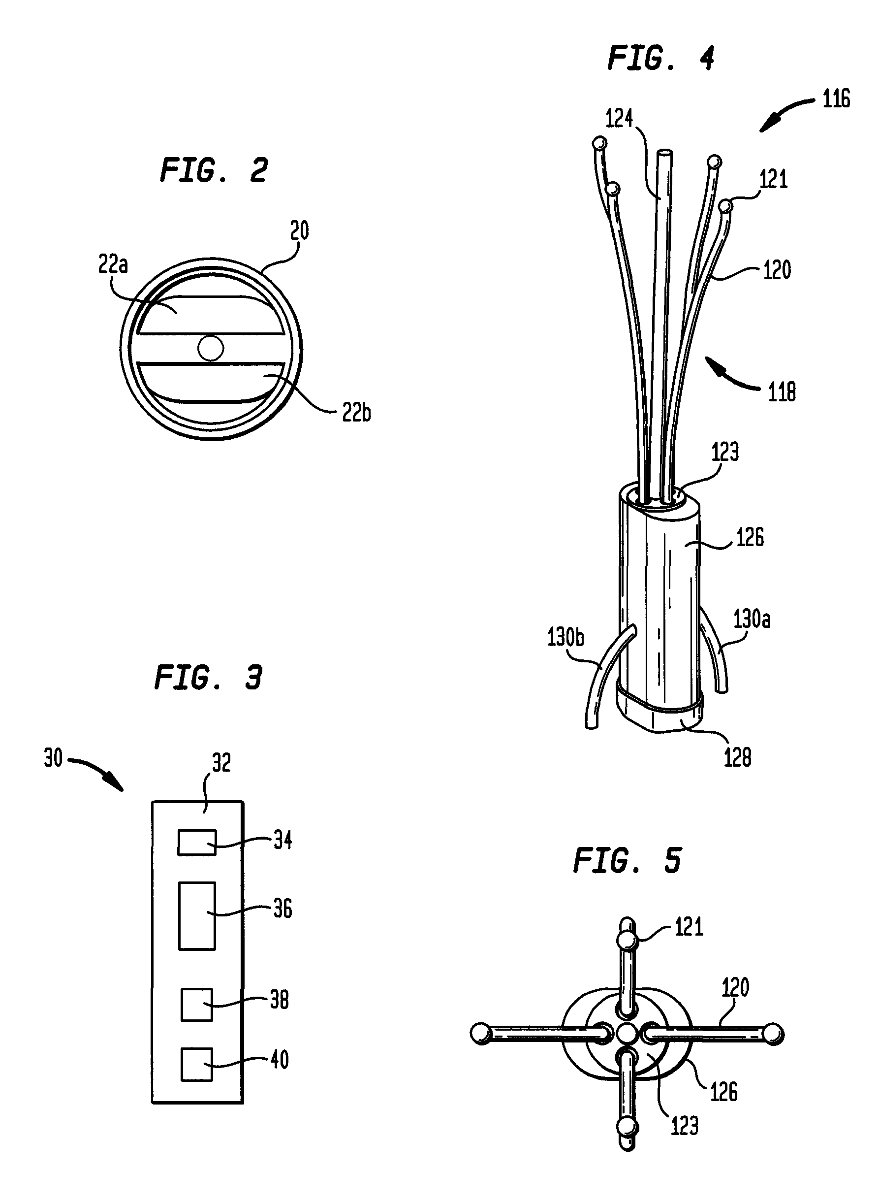
[0041]FIG. 4 illustrates a monitoring unit 116 according to the present invention. In this embodiment, the support rod 118 features a set of four equidistantly spaced flexible nesting wires 120 having bulbous terminal ends 121. All of the nesting wires 120 are supported by a plate 123. A central bar 124 projects upward from the plate and is arranged interior to all of the nesting wires. Unitarily molded with the plate, central bar and nesting wires is a retention cage 126. An interior of the retention cage is hollow to receive a logger. Flowable material is prevented from entering the retention cage by a cap 128 sealing an opening of the retention cage. A pair of stabilization wires 130a, 130b are unitarily molded with walls of the retention cage and project outwardly therefrom in opposite directions to one another. The function of the stabilizing wires is to prevent the monitoring unit from moving about in the container body.
[0042]FIG. 5 illustrates a top down view of monitoring un...
third embodiment
[0043]FIG. 6 illustrates a monitoring unit 216. The unit includes a support rod 218 formed with a nesting ring 220. A pair of arms 222a, 222b connect opposite sections of the nesting ring to a central bar 224. A projection 225 shaped as a cross is unitarily molded at an end of the central bar distant from the end with the arms. A variety of shapes different from that of a cross may be utilized as the projection. For instance, a round, oval or any polygonal structure would be suitable as a projection. Separate from the combination of support rod, nesting ring, arms, central bar and projection is a retention cage 226 formed with a rectangular beam 228 with unitarily molded plastic clip members 229a, 229b and at opposite ends of the beam a pair of brackets 231a, 231b. A logger 230 is secured within the clip members and brackets. The beam 228 has a hollow receiving area 232 of a shape complementary to that of the projection 225.
[0044]FIG. 7 illustrates the third embodiment of the monito...
PUM
 Abstract
Description
Claims
Application Information
 - R&D
- Intellectual Property
- Life Sciences
- Materials
- Tech Scout
- Unparalleled Data Quality
- Higher Quality Content
- 60% Fewer Hallucinations
Browse by: Latest US Patents, China's latest patents, Technical Efficacy Thesaurus, Application Domain, Technology Topic, Popular Technical Reports.
© 2025 PatSnap. All rights reserved.Legal|Privacy policy|Modern Slavery Act Transparency Statement|Sitemap|About US| Contact US: help@patsnap.com


