Treatment instrument for endoscope including a sheath having a tapered portion at a distal end portion thereof
a treatment instrument and endoscope technology, applied in the field of endoscope treatment instruments, can solve the problems of poor visibility of the distal end electrode portion and the axial electrode that are on the extension of the distal end portion of the sheath as well as a treatment site, and it is difficult to insert the distal end electrode portion into the submucosa from the dissected mucosa, so as to achieve safe and easy ablation of mucosa or submu
- Summary
- Abstract
- Description
- Claims
- Application Information
AI Technical Summary
Benefits of technology
Problems solved by technology
Method used
Image
Examples
second embodiment
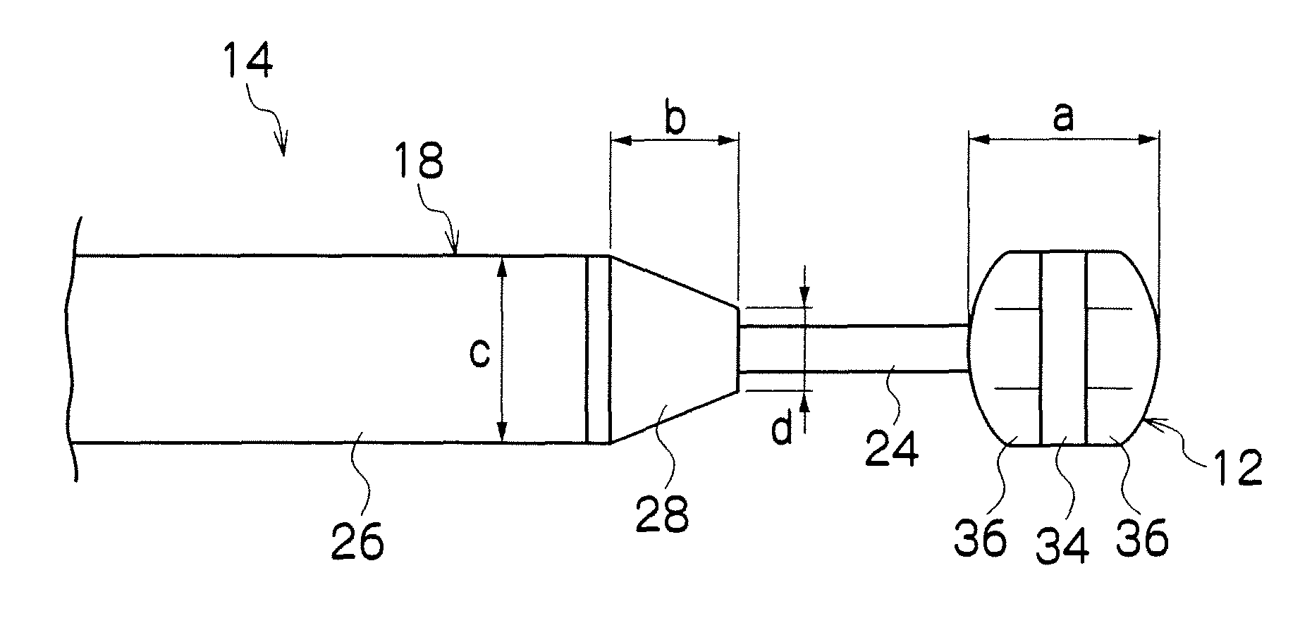
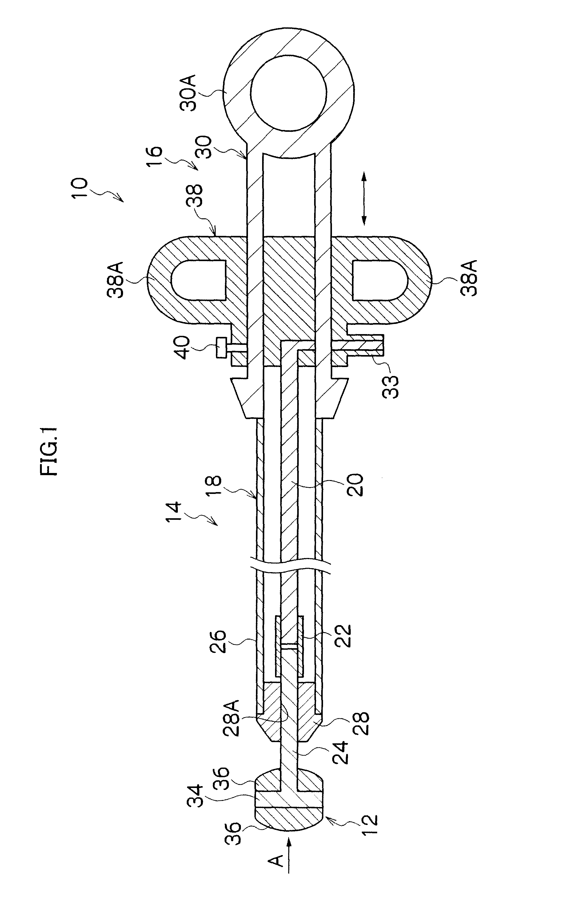
[0076]FIG. 9 is a side view that illustrates a treatment instrument for an endoscope according to the In FIG. 9, members that are the same as, or similar to, members of the treatment instrument 10 for an endoscope shown in FIG. 3 are designated by the same reference numerals, and a description of those members is omitted.
[0077]In the treatment instrument for an endoscope shown in FIG. 9, a flat face 31A that is substantially parallel with the protrusion / retraction direction of the axial electrode 24 is formed at the distal end portion of the sheath 18, that is, at the distal end portion of the collar member 28, and an end face 31B of the flat face 31A is formed in a largish fashion. When the axial electrode 24 is retracted into the sheath 18, a rear end face 36A of the non-conductive portion 36 on the proximal end side of the distal end electrode portion 12 has surface contact with the end face 31B. Therefore, the distal end electrode portion 12 is stably retained by the end face 3...
third embodiment
[0079]For example, a distal end electrode portion 112 shown in FIG. 10 and FIG. 11 which show the third embodiment is formed in a shape in which four plate members are combined in the shape of a cross. More specifically, in a main unit 114 of the distal end electrode portion 112, four non-conductive plate members are disposed at 90° intervals to form a cross shape that connects with a central shaft side of the distal end electrode portion 114.
[0080]On the distal end side of the main unit 114, four protruded portions 114A, 114A, . . . are formed by each plate member protruding to the distal end side, and depressed portions 114B, 114B, . . . are formed at center positions between each of the protruded portions 114A, 114A, . . . . Similarly, on the proximal end side of the main unit 114, protruded portions 114C, 114C, . . . are formed by each plate member protruding to the proximal end side, and depressed portions 114D, 114D, . . . are formed at center positions between each of the pro...
PUM
 Abstract
Description
Claims
Application Information
 - R&D
- Intellectual Property
- Life Sciences
- Materials
- Tech Scout
- Unparalleled Data Quality
- Higher Quality Content
- 60% Fewer Hallucinations
Browse by: Latest US Patents, China's latest patents, Technical Efficacy Thesaurus, Application Domain, Technology Topic, Popular Technical Reports.
© 2025 PatSnap. All rights reserved.Legal|Privacy policy|Modern Slavery Act Transparency Statement|Sitemap|About US| Contact US: help@patsnap.com


