Single-mode optical fiber

a single-mode, optical fiber technology, applied in the field of optical fiber transmission, can solve the problems of not meeting the requirements of the itu-t, and commercially incompatible optical fiber with certain transmission systems, so as to facilitate the optical fiber fabrication process to be more flexible and flexible, reduce bending losses, and reduce bending losses

Active Publication Date: 2013-04-23
DRAKA COMTEQ BV
View PDF126 Cites 42 Cited by
  • Summary
  • Abstract
  • Description
  • Claims
  • Application Information

AI Technical Summary

Benefits of technology

[0027]In this regard, the present invention embraces an optical-fiber profile that includes a central core, an intermediate cladding, and a buried trench. The core employs a parabolic profile (e.g., an alpha-index profile) instead of a step-index profile. It has been observed that the parabolic-index profile enables reduced bending losses (e.g., by as much as 30 percent) compared with a step-index profile, with the mode field diameter (MFD), cable...

Problems solved by technology

Unfortunately, reducing the MAC value by reducing the mode diameter and/or by increasing the fiber cut-off wavelength (λC) can lead to noncompliance with the ITU-T G.652 recommendations, thereby making an optical fiber commercially incompatible with certain transmission systems.
Accordingly, reducing bending losses while remaining compliant with industry recommendations constitutes a genuine chall...

Method used


Image

  • Single-mode optical fiber
  • Single-mode optical fiber
  • Single-mode optical fiber

Examples


Embodiment Construction

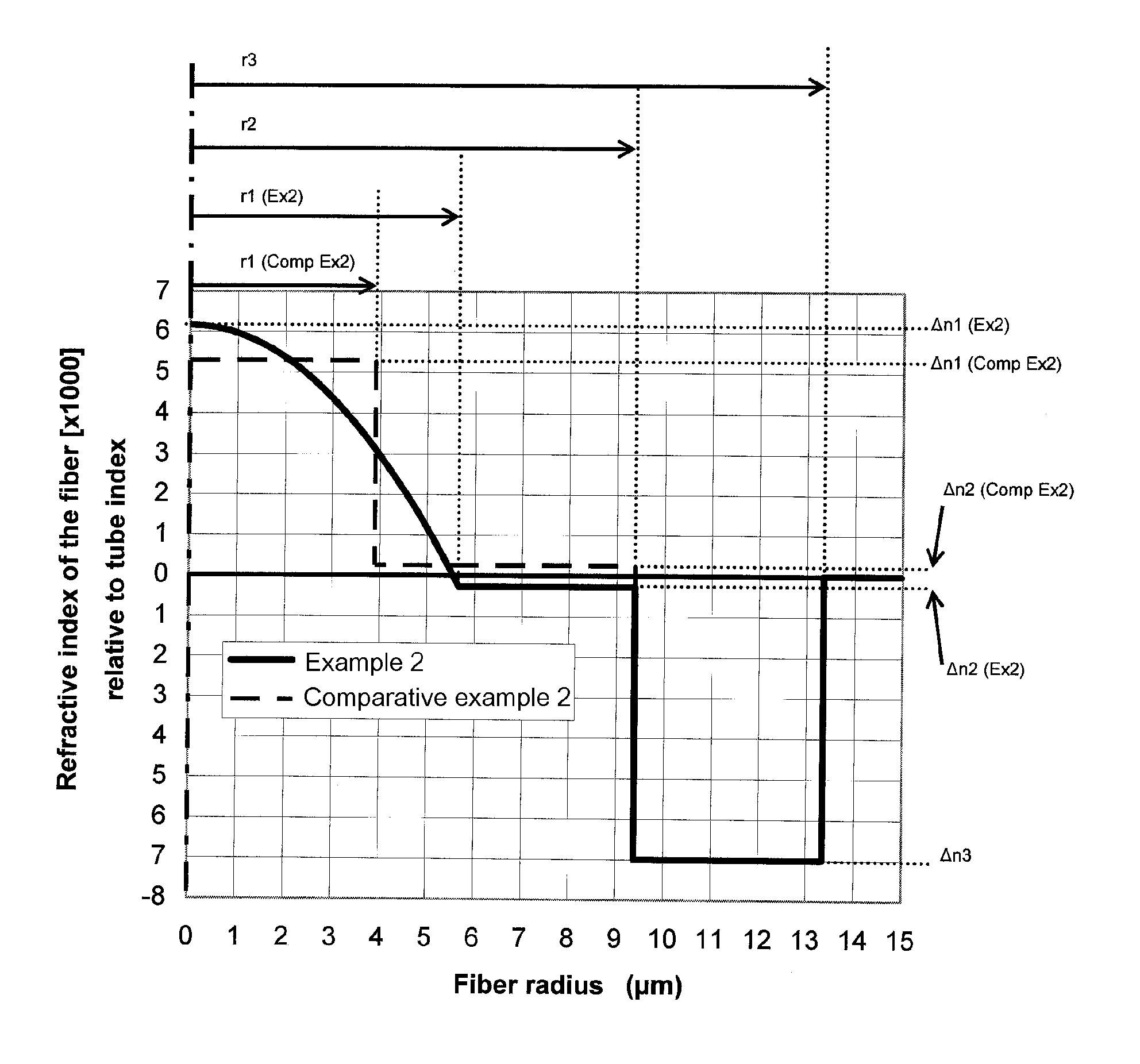
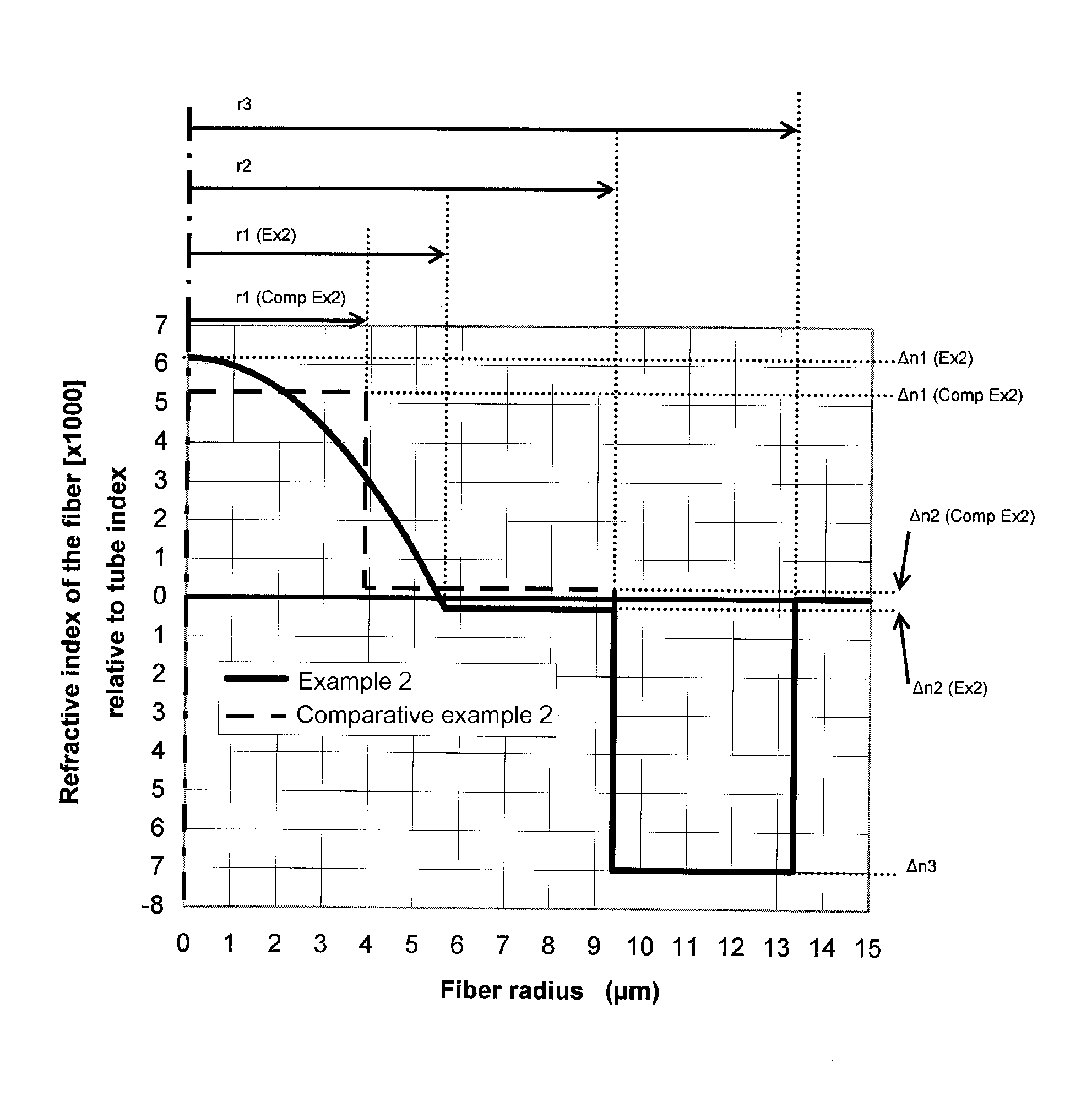
[0053]In one aspect, the present invention embraces an optical fiber that includes (i) a central core, (ii) an intermediate cladding, (iii) a buried trench (e.g., a depressed cladding), and (iv) an outer cladding.

[0054]The central core has a radius r1 and an index difference Δn(r) relative to the outer cladding, which acts as an optical cladding. The refractive index of the core typically has a parabolic shape. Accordingly, the refractive-index difference Δn(r) between the central core and the outer cladding depends on the distance r from the center of the optical fiber (e.g., decreasing as the distance from the center of the optical fiber increases). Thus, the central core defines a maximum refractive-index difference Δn1 with respect to the outer cladding. As used herein, the term “refractive-index difference” does not exclude a refractive-index difference of zero.

[0055]The intermediate cladding has (i) a radius r2 and (ii) a refractive-index difference Δn2 with respect to the out...


PUM


Abstract

The present invention embraces a single-mode optical fiber typically having reduced bending losses. The optical fiber includes a central core, an intermediate cladding, a buried trench, and an outer cladding. The optical fiber typically has (i), at a wavelength of 1310 nanometers, a mode field diameter with a nominal value of between about 8.6 microns and 9.5 microns (and a tolerance of ±0.4 micron), (ii) a cable cut-off wavelength of no more than 1260 nanometers, and (iii), for a bending radius of 15 millimeters at a wavelength of 1550 nanometers, bending losses of no more than 0.03 dB/turn.

Description

CROSS-REFERENCE TO PRIORITY APPLICATION[0001]This application hereby claims the benefit of pending French application No. 10 / 51879 (filed Mar. 17, 2010, at the National Institute of Industrial Property (France)), which is hereby incorporated by reference in its entirety.FIELD OF THE INVENTION[0002]The present invention relates to the field of optical-fiber transmission and, more specifically, to an optical fiber having reduced bending losses.BACKGROUND[0003]An optical fiber's refractive-index profile is generally described as a relationship of refractive index and the optical fiber's radius. Conventionally, the distance r from the center of the optical fiber is plotted along the abscissa (i.e., the x axis), and the difference between the refractive index at a distance r and the refractive index of the outer cladding of the optical fiber is plotted along the ordinate (i.e., the y axis). The outer cladding, functioning as an optical cladding, typically has a refractive index that is s...

Claims


Application Information

Patent Timeline
IPC IPC(8): G02B6/028G02B6/036
CPCG02B6/0281G02B6/0365G02B6/02242G02B6/02395
Inventor DE MONTMORILLON, LOUIS-ANNERICHARD, SIMONSILLARD, PIERRE
Owner DRAKA COMTEQ BV
Why Eureka
Try Eureka