Electric blower and electric vacuum cleaner equipped with the electric blower

A vacuum cleaner and blower technology, applied in the direction of machines/engines, liquid fuel engines, pumping devices for elastic fluids, etc., can solve the problems of increased air flow loss, faster flow velocity at bending parts, and air flow turbulence, etc. Achieve the effect of increasing suction power and suppressing peeling

Active Publication Date: 2016-01-20
HITACHI APPLIANCES INC
View PDF5 Cites 0 Cited by
  • Summary
  • Abstract
  • Description
  • Claims
  • Application Information

AI Technical Summary

Problems solved by technology

Due to the through hole, the air flow is disturbed at the outlet of the diffuser and the inlet of the ball return on the opposite load side, and the loss of air flow at this bending part increases, and the efficiency of the electric blower decreases
[0012] In Patent Document 2, since the airflow flowing out from the diffuser has a radial velocity component, peeling is likely to occur at the incision from the outer peripheral end of the diffuser blade along the surface on the outer peripheral side of the diffuser blade, making it impossible to effectively inflow cut
That is, since air does not flow due to peeling at the incision, the flow velocity at the curved portion may increase, increasing bending loss, and reducing the efficiency of the electric blower.

Method used


Image

  • Electric blower and electric vacuum cleaner equipped with the electric blower
  • Electric blower and electric vacuum cleaner equipped with the electric blower
  • Electric blower and electric vacuum cleaner equipped with the electric blower

Examples


Embodiment 1

[0039] like Figure 13As shown in the perspective view of the exterior, the electric vacuum cleaner includes an electric vacuum cleaner main body 100 with a built-in electric blower and a dust collection filter, a hose 101 that is rotatably connected to the electric vacuum cleaner main body 100 at one end, and a hose 101 at the other end of the hose 101. The hose handle 102 , the extension tube 103 with one end provided at the other end of the hose handle 102 , and the suction port 104 installed at the other end of the extension tube 103 . The hose handle part 102 is provided with the switch operation part 105 for controlling the electric blower in the vacuum cleaner main body 100. As shown in FIG.

[0040] Next, use Figure 12 The vertically sectional side view of the vacuum cleaner main body 100 of the illustrated vacuum cleaner illustrates the vacuum cleaner main body 100 .

[0041] The electric vacuum cleaner main body 100 is composed of a lower casing 106 , an upper cas...

Embodiment 2

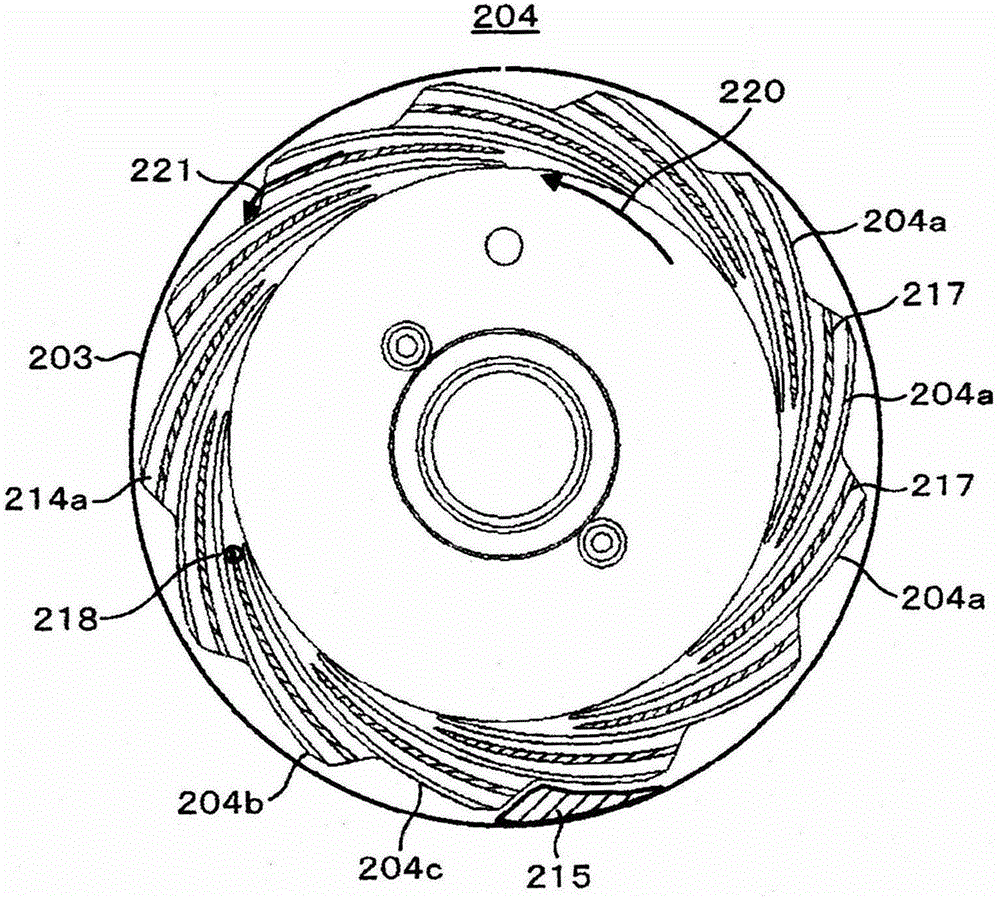
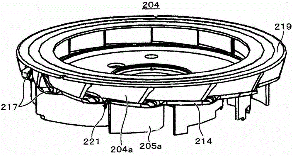
[0063] Next, use Figure 7 , Figure 8 An embodiment of the present invention will be described. Figure 7 is a top view of one embodiment of diffuser 204, Figure 8 is a perspective view of diffuser 204 . Since the basic structure is the same as that of the above-mentioned embodiments, the same symbols are used for the same elements and their descriptions are omitted.

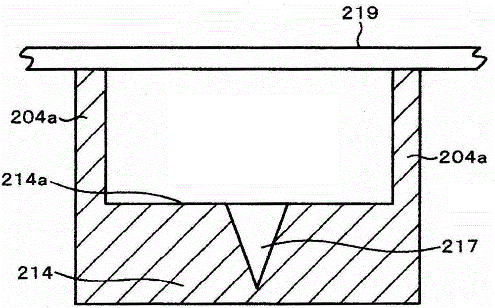
[0064] In this embodiment, there is a coincident length portion 223 adjacent to the inlet neck 218 defined by the front edge portion of the diffuser 204a and surrounded by the outlet neck 222 defined by the rear edge portion of the diffuser 204a, provided from At about 1 / 5 of the length of the overlapping length portion 223 of the diffuser 204a adjacent to the partition plate 214 on the hub surface 214a side of the diffuser of the flow path formed by the diffuser 204a and the partition plate 214 in the circumferential direction to The outer peripheral end has a concave portion having a width approximately ...


PUM


Abstract

The invention provides an electric blower and an electric dust collector installed with the electric blower. The efficiency of the electric blower is improved by reducing the flow rate at a bent portion from a diffuser to a ball returning device and turning the flow smoothly to reduce the bending loss. Further, by improving the efficiency of the electric blower, the sucking power, i.e. output, is enhanced. The electric blower is provided with a separation plate, a plurality of ball returning vanes disposed on one surface of the separation plate, a plurality of diffuser vanes disposed on the other surface of the separation plate, and an electric motor. The other surface of the separation plate is provided with a recess. Flow channels are disposed by adjacent diffuser vanes in the plurality of diffuser vanes and the separation plates. The recess portion is set to be an end portion from the flow channel to the outer peripheral of the separation plate.

Description

technical field [0001] The invention relates to an electric blower and an electric vacuum cleaner equipped with the electric blower. Background technique [0002] As a conventional electric blower for an electric vacuum cleaner, for example, there is an electric blower disclosed in JP-A-2007-270633 (Patent Document 1). [0003] Japanese Patent Application Laid-Open No. 2007-270633 describes the following electric blower: the electric blower is equipped with a motor, a centrifugal impeller mounted on the rotating shaft of the motor, a diffuser blade located around the centrifugal impeller, and the blown air from the centrifugal impeller is blown. The rectified diffuser and the fan case covering the centrifugal impeller and the diffuser are provided on the outer peripheral side of the channel bottom surface formed between the diffuser blades of the diffuser and near the outer peripheral end to connect the load side and the anti-load side of the diffuser. hole. [0004] Accor...

Claims


Application Information

Patent Timeline
Patent Type & Authority Patents(China)
IPC IPC(8): F04D29/00F04D29/28F04D29/44
Inventor 坂上诚二常乐文夫西冈嘉之本多武史冯益祥伊藤贤宏
Owner HITACHI APPLIANCES INC
Why Eureka
Try Eureka