Method for determining at least one displacement state of a vehicle body

a technology of vehicle body and displacement state, which is applied in the field of process for determining at least one state of motion of the vehicle body, can solve the problems of increasing design effort, high cost, and inability to achieve the vertical dynamic regulation of the body according to the gps principle, and achieves the effect of improving the control of the suspension and high accuracy

Active Publication Date: 2013-04-23
ZF FRIEDRICHSHAFEN AG
View PDF27 Cites 3 Cited by
  • Summary
  • Abstract
  • Description
  • Claims
  • Application Information

AI Technical Summary

Benefits of technology

[0012]An object of the present invention is to determine at least one state of motion of the vehicle body with high accuracy with the use of a path or angle sensor and an acceleration sensor, while the design effort, especially the space needed for the installation of the sensor system, can be reduced. The knowledge of this state of motion can then be used to better control the suspension of the vehicle.

Problems solved by technology

The definition of the position of the body according to the GPS principle is, in general, not realistic at present for the vertical dynamic regulation of the body due to the requirements imposed on accuracy and the requirement imposed in terms of availability.
By contrast, vehicle-mounted optoelectronic sensor systems are complicated and can therefore be used mainly for technical measuring tasks.By relative measurement, i.e., by means of a sensor system, which is arranged in the area of the wheel suspension and / or the body and which determines the relative position between the transducer element and a sensor according to a magnetic or electrical principle of operation.
Especially the latter is usually possible, due to the error of the sensor signal, with a great effort only by the use of special filtering techniques.
However, the use of a body-side acceleration sensor combined with chassis-side distance sensors leads to an increased design effort and relatively high costs.
Furthermore, the alternative determination of the velocity of the vehicle body from a damper velocity signal with the wheel velocity component filtered out is inaccurate.

Method used


Image

  • Method for determining at least one displacement state of a vehicle body
  • Method for determining at least one displacement state of a vehicle body
  • Method for determining at least one displacement state of a vehicle body

Examples


Embodiment Construction

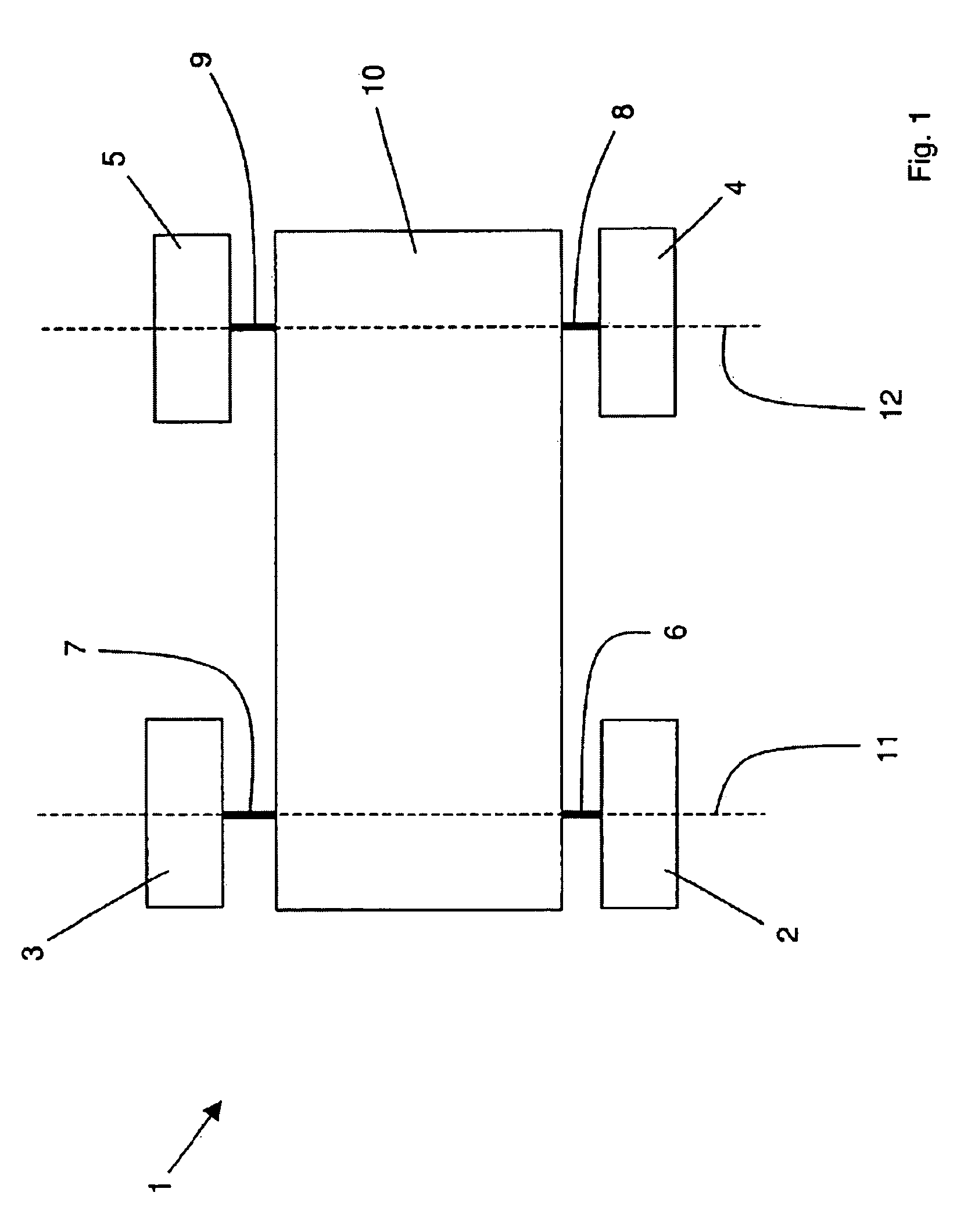
[0082]Referring to the drawings in particular, FIG. 1 shows a schematic top view of a vehicle 1 according to an embodiment of the present invention, in which four wheels 2, 3, 4 and 5 are connected to a vehicle body 10 via a wheel suspension 6, 7, 8 and 9 each. The two wheels 2 and 3 are part of a front axle (FA) 11 and the two wheels 4 and 5 are part of a rear axle (RA) 12.

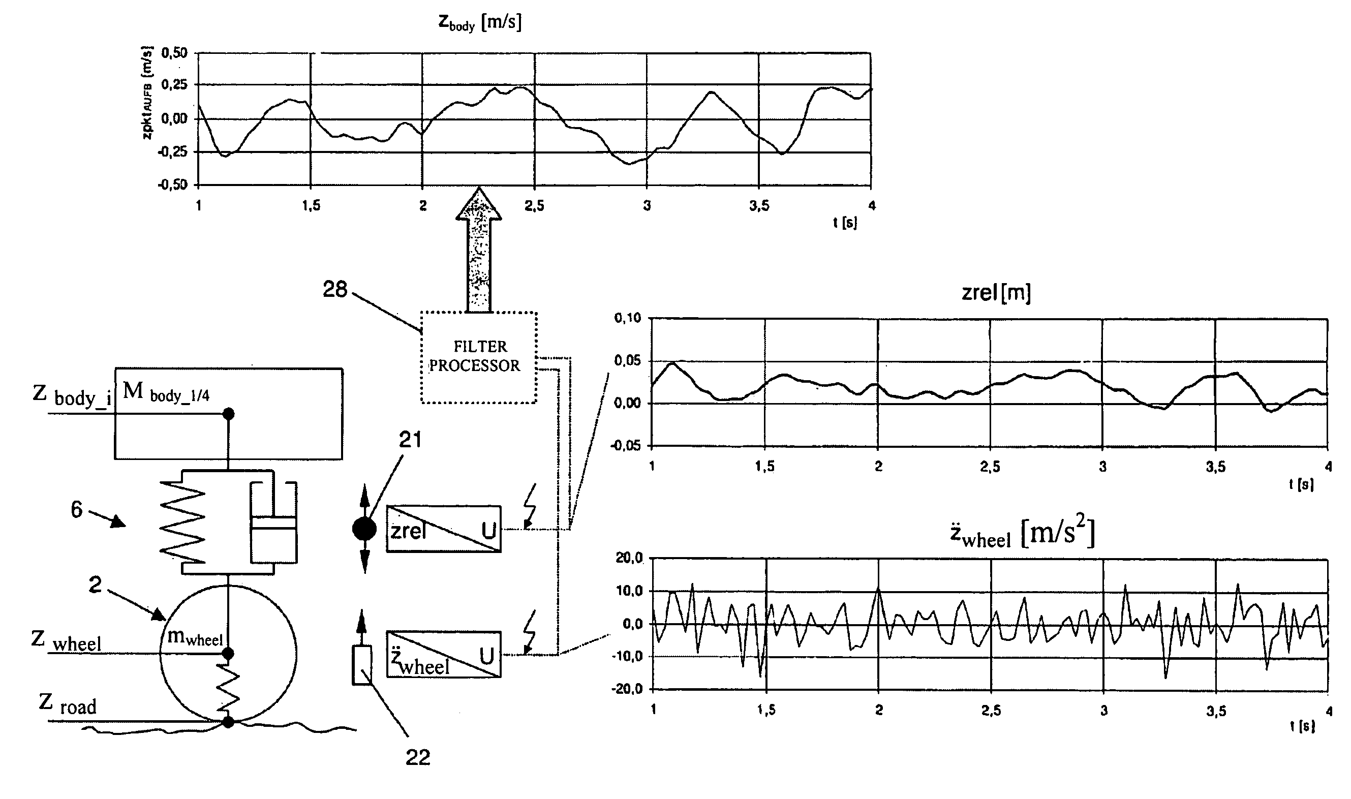
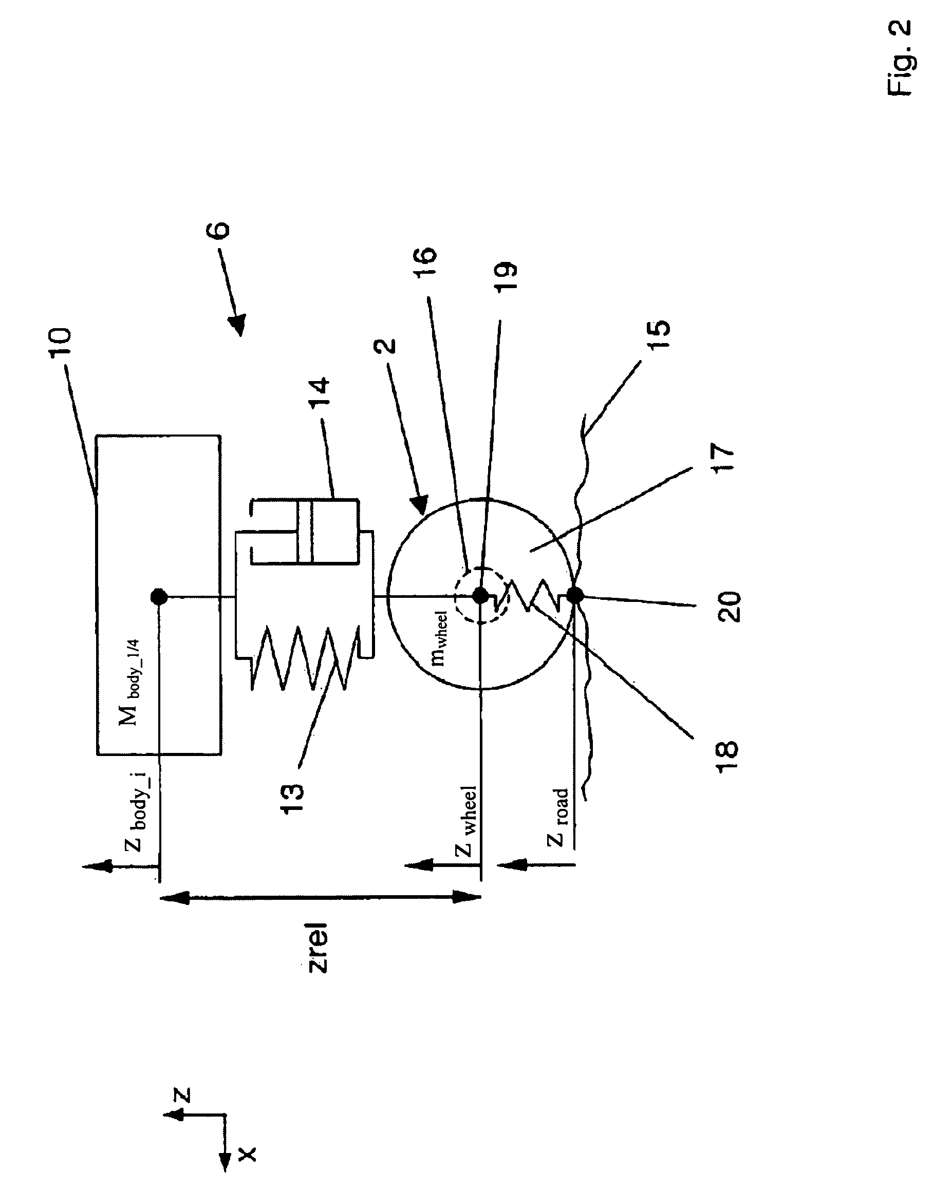
[0083]FIG. 2 shows a schematic view of the wheel suspension 6, in which wheel 2 is connected to the vehicle body 10 via a vehicle spring 13 and via a shock absorber 14. Wheel 2 is in contact with a pavement or road surface 15 with a tire 17 and has a wheel carrier 16 connected to the spring 13 and to the shock absorber 14. The tire 17, which is preferably filled with air, forms a spring 18, which acts and is arranged between the road surface 15 and the wheel carrier 16. Wheel 2 is in contact with the road surface 15 via a wheel contact point 20 and has a central axis or axis of rotation 19.

[0084]Furthermore, the ...


PUM

PropertyMeasurementUnit
frequenciesaaaaaaaaaa
massaaaaaaaaaa
velocityaaaaaaaaaa

Abstract

Process for determining at least one state of motion of a vehicle body (10) of a vehicle (1), which has at least one wheel (2) spring-mounted on the vehicle body (10) via a wheel suspension (6), whereinan inward deflection (zrel) of the wheel (2) is measured by means of a path or angle sensor (21),an inward deflection velocity (żrel) of the wheel (2) is determined by differentiating the inward deflection (zrel) of the wheel (2) over time,a vertical acceleration ({umlaut over (z)}wheel) of the wheel (2) is measured by means of an acceleration sensor (22),a vertical velocity (żwheel) of the wheel (2) is determined by integrating the vertical acceleration ({umlaut over (z)}wheel) of the wheel (2) over time, anda vertical velocity (żbody) of the vehicle body (10) is calculated by forming a difference of the vertical velocity (żwheel) of wheel (2) and the inward deflection velocity (żrel) of wheel (2).

Description

CROSS REFERENCE TO RELATED APPLICATIONS[0001]This application is a United States National Phase application of International Application PCT / DE2007 / 000047 and claims the benefit of priority under 35 U.S.C. §119 of German patent application 10 2006 001 436.7 filed 10 Jan. 2006, the entire contents of which are incorporated herein by reference.FIELD OF THE INVENTION[0002]The present invention pertains to a process for determining at least one state of motion of a vehicle body of a vehicle, which has at least one wheel spring-mounted on the vehicle body via a wheel suspension, wherein an inward deflection of the wheel is measured by means of a path or angle sensor, and a velocity of inward deflection of the wheel is determined by the time differentiation of the inward deflection of the wheel. The present invention pertains, furthermore, to a vehicle with a vehicle body, at least one wheel, which is spring-mounted on the vehicle body via a wheel suspension, at least one acceleration sen...

Claims


Application Information

Patent Timeline
Patent Type & Authority Patents(United States)
IPC IPC(8): G01M17/00C07C5/00G06F19/00G06F7/00G06F11/30
CPCB60G17/0165B60G17/019B60G17/018B60G2800/916B60G2204/11B60G2204/416B60G2400/102B60G2400/202B60G2400/206B60G2400/252B60G2400/821B60G2400/91B60G2600/14B60G2600/16B60G2800/162B60G2800/702B60G17/015
Inventor GARTNER, ANDREASHEES, EBERHARDRAPPELT, STEFAN
Owner ZF FRIEDRICHSHAFEN AG
Why Eureka
Try Eureka