
Heating cooker with hinged door

a technology of hinged doors and cookers, applied in the field of heating cookers, to achieve the effect of improving convenience for users

Inactive Publication Date: 2013-04-30
SAMSUNG ELECTRONICS CO LTD
View PDF20 Cites 10 Cited by
  • Summary
  • Abstract
  • Description
  • Claims
  • Application Information

AI Technical Summary

Benefits of technology

Enables the door to be opened automatically without manual rotation, enhancing user convenience by allowing hands-free operation and controlling the opening speed to prevent sudden or forceful door opening.

Problems solved by technology

For the conventional heating cooker described in Korean Patent Application No. 2005-0060560, since opening and closing of the door can be realized only by manual handling, there is an inconvenience in that, when opening the door with something held in the user's hand, it is necessary for the user to grip the handle and rotate the door downward.

Method used


Image

  • Heating cooker with hinged door
  • Heating cooker with hinged door
  • Heating cooker with hinged door

Examples


first embodiment

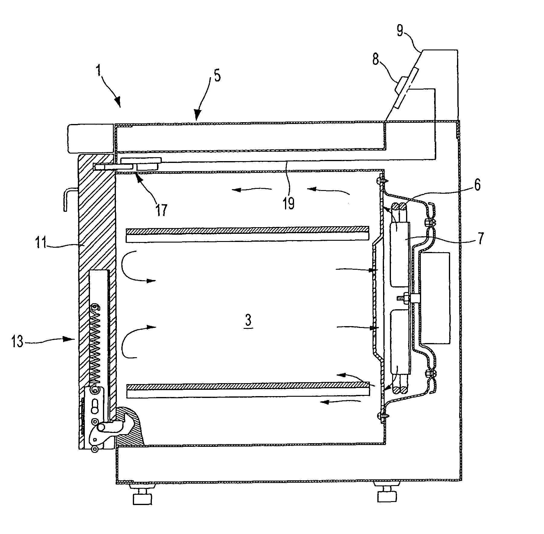
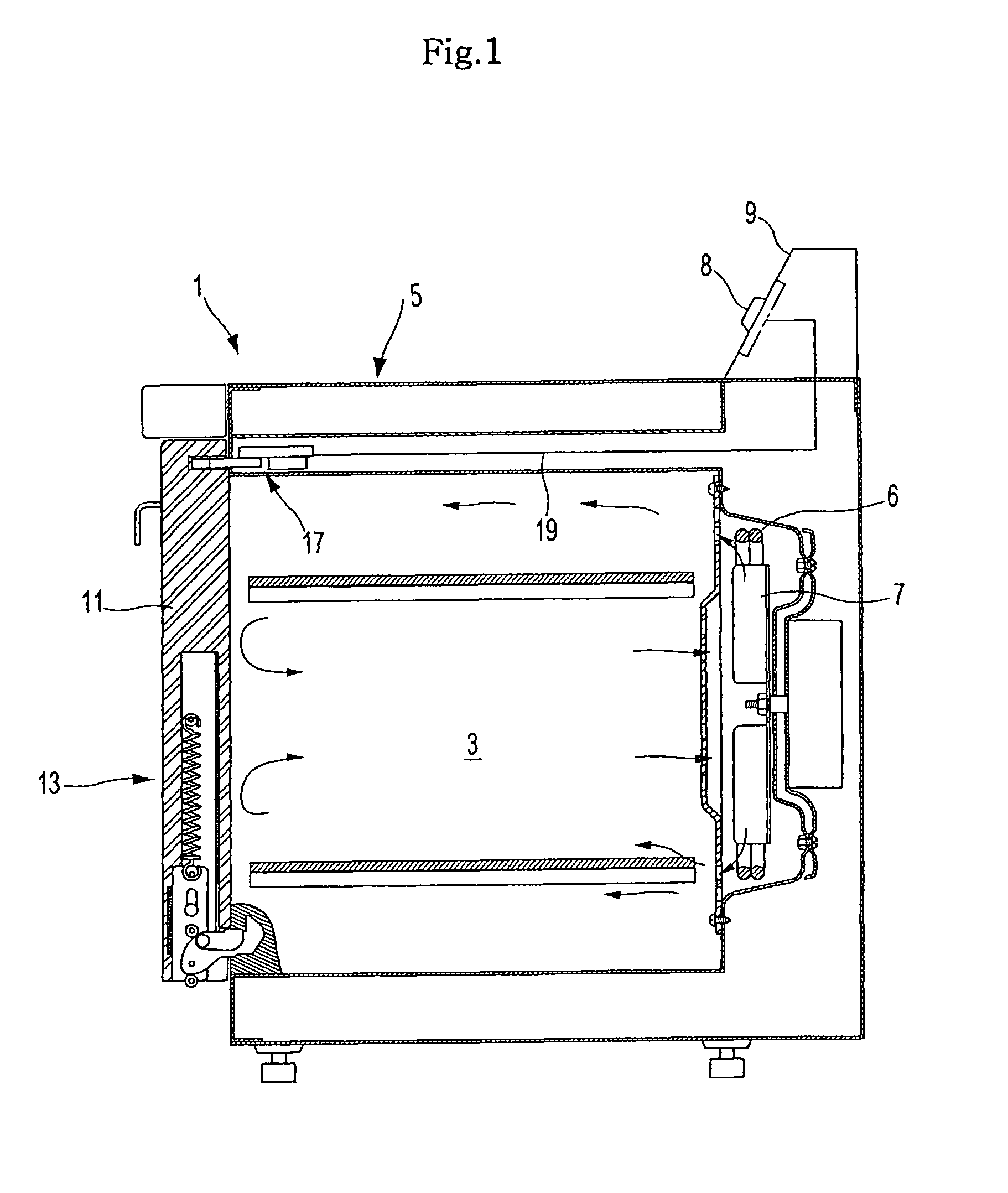
[0038]Referring to FIG. 1, a heating cooker according to the invention includes a body 1 constituting an appearance of the heating cooker and having a cooking chamber 3 defined therein, a heater 6 and a convection fan 7 positioned at a rear of the cooking chamber 3, and a burner 5 and a control panel 9 with an input button 8 and the like disposed thereon at an upper portion of the body 1.

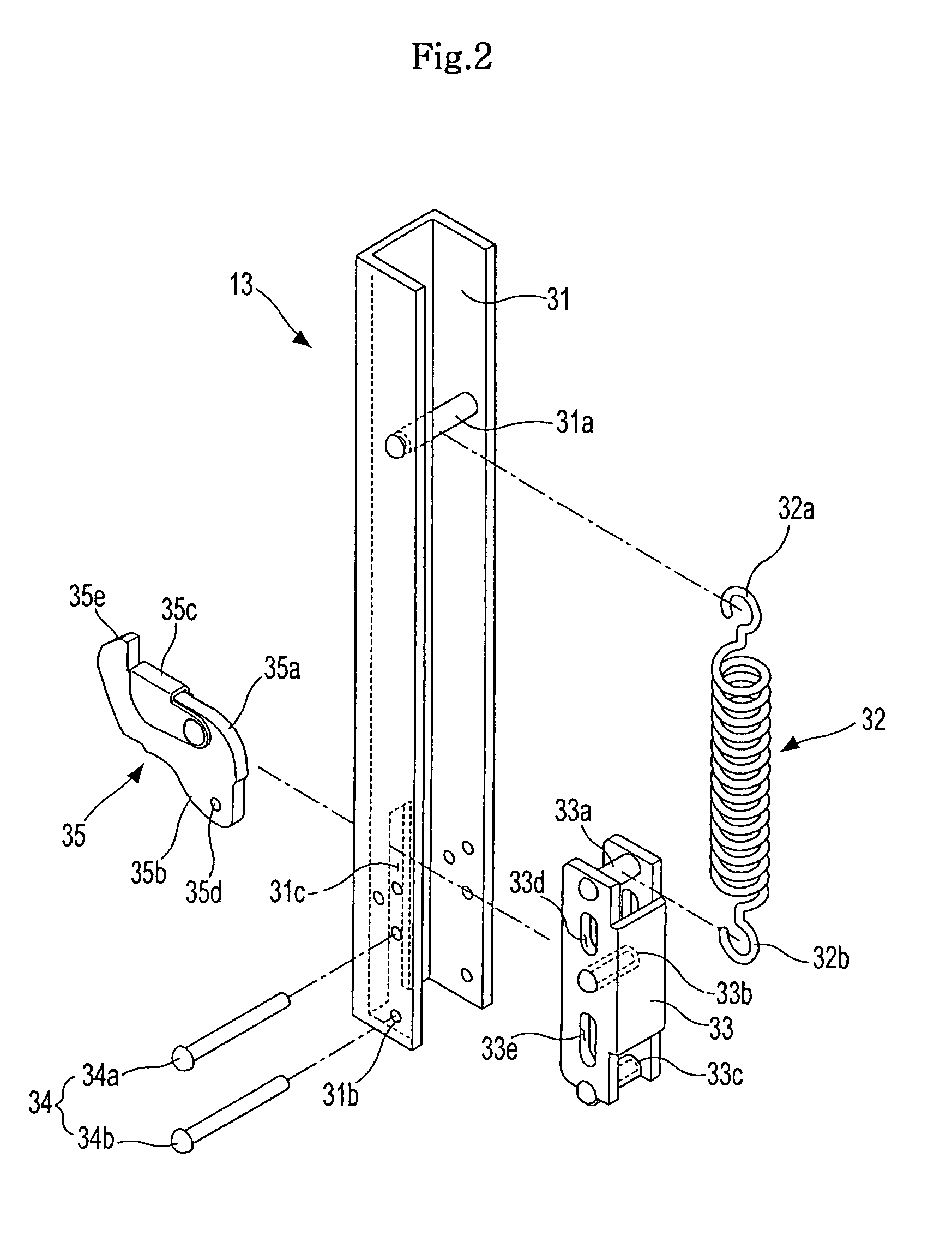
[0039]The body 1 includes a door 11 rotatably mounted to a front side of the body 1 to open and close a front side of the cooking chamber 3, and a hinge part 13 positioned at a lower end of the door 11 to hingably connect the door 11 to the body 1 while allowing rotation of the door 11.

[0040]A door holder 17 is positioned between the cooking chamber 3 and the burner 5 and is coupled to the door 11 to hold the door 11 such that the door holder 17 can keep the cooking chamber 3 closed by the door 11 when the door 11 closes the cooking chamber 3. Here, the door holder 17 is connected to the control pan...

second embodiment

[0059]In the second embodiment, the door 11 closes the cooking chamber 3 (see FIG. 1) by a magnetic force generated from the electromagnet 70 to attract the attachment member 72. Thus, when the magnetic force is removed from the electromagnet 70 by operation of the user, the door 11 is spontaneously rotated forwardly, opening the cooking chamber 3.

third embodiment

[0060]FIG. 5 shows a heating cooker according to the present invention, which employs only mechanical components in place of the driving motor and the magnet.

[0061]The door 11 is provided with a stepped button 73, a connecting bar 74 connected to a rear of the button 73, a supporting plate 75 to support the connecting bar 74 while allowing the connecting bar 74 to move up and down, and a return spring 76 between the button 73 and the supporting plate 75 to allow the button 73 and the connecting bar 74 connected to the button 73 to return to their home positions when a force pushing the button 73 is removed.

[0062]The connecting bar 74 is provided at an end with a latch hook 63′ which has a bent middle portion, around which the latch hook 63′ is allowed to rotate in response to up and down movements of the connecting bar 74.

[0063]The body 1 of the heating cooker is provided at a front side with a latch groove 77 to which the latch hook 63′ is latched, so that the door 11 closes or ope...


PUM


Abstract

Provided is a heating cooker which allows a door on a cooking chamber to be opened without direct handling of the door by a user. The heating cooker includes a body having a cooking chamber defined therein, a door hingably mounted to the body to open and close the cooking chamber, a door holder positioned in the body to hold the door and keep the cooking chamber closed by the door, and a hinge part connected between the door and the body to guide rotation of the door such that when the door is released from the door holder, the door is automatically opened.

Description

CROSS-REFERENCE TO RELATED APPLICATIONS[0001]This application claims priority from Korean Patent Application No. 2006-0094956, filed on Sep. 28, 2006 in the Korean Intellectual Property Office, the disclosure of which is incorporated herein by reference.BACKGROUND OF THE INVENTION[0002]1. Field of the Invention[0003]The present invention relates to a heating cooker, and, more particularly, to a heating cooker, which allows a door on a cooking chamber to be opened without requiring a user to directly pull the door, thereby improving convenience in use to the user.[0004]2. Description of the Related Art[0005]One example of a conventional heating cooker is disclosed in Korean Patent Application No. 2005-0060560, and includes a body having a cooking chamber defined therein, a door hingably mounted to the cooking chamber to open and close the cooking chamber, and a handle positioned on the door to be gripped by a user when opening and closing the door.[0006]To open and close the opening ...

Claims


Application Information

Patent Timeline
Patent Type & Authority Patents(United States)
IPC IPC(8): F23M7/00
CPCF24C7/082F24C15/022Y10T16/585Y10T16/2796Y10T16/287Y10T16/304F24C7/085E05Y2900/308E05Y2201/408E05F1/1276E05F5/02E05F5/08E05Y2201/21E05Y2201/22E05Y2201/47E05D11/10F24C7/043F24C15/023F24C15/027F24C15/028
Inventor KIM, SUNG KWANGHAN, DAE SUNGKWON, YONG HYUNHONG, SEOK WEONLEE, TAE UKCHO, PUNG YEUNKANG, HAN SEONGPARK, SUNG SOOSUNG, HAN JUNKIM, TAE HUN
Owner SAMSUNG ELECTRONICS CO LTD
Learn More