Turbofan gas turbine engine

a gas turbine engine and turbine technology, applied in the direction of liquid fuel engines, machines/engines, elastic bearings, etc., can solve the problems of reduced efficiency, fan damage, and fan damage,

Active Publication Date: 2013-04-30
ROLLS ROYCE PLC
View PDF37 Cites 27 Cited by
  • Summary
  • Abstract
  • Description
  • Claims
  • Application Information

AI Technical Summary

Problems solved by technology

The fan is vulnerable to damage as a result of foreign objects entering the turbofan gas turbine engine.
In most cases, the fan is sufficiently robust to withstand the effects of such foreign object ingestion without suffering major damage and is able to continue operating, although, perhaps, at reduced efficiency.
On very rare occasions, the fan may be damaged to such an extent that parts of one or more of the fan blades that make up the fan are lost.
However, the imbalance in the fan created by the fan blade loss initially generates extremely high loads, which must, at least partially, be absorbed as the gas turbine engine is allowed to run-down to windmilling speed.
The transients following the fan blade loss produce massive loads and distortion of the bearing housing for the fan bearing and also in surrounding structure.
However, this results in a heavily reinforced structure both in the engine and aircraft, which results in an increase in weight of the engine and aircraft.
Again, this results in an increase in weight of the engine and aircraft and the movement of the energy absorbing links or deforming housings results in permanent deformation of the structure and does not give a stiff structure to control shaft / rotor dynamics during windmilling.

Method used


Image

  • Turbofan gas turbine engine
  • Turbofan gas turbine engine
  • Turbofan gas turbine engine

Examples


Embodiment Construction

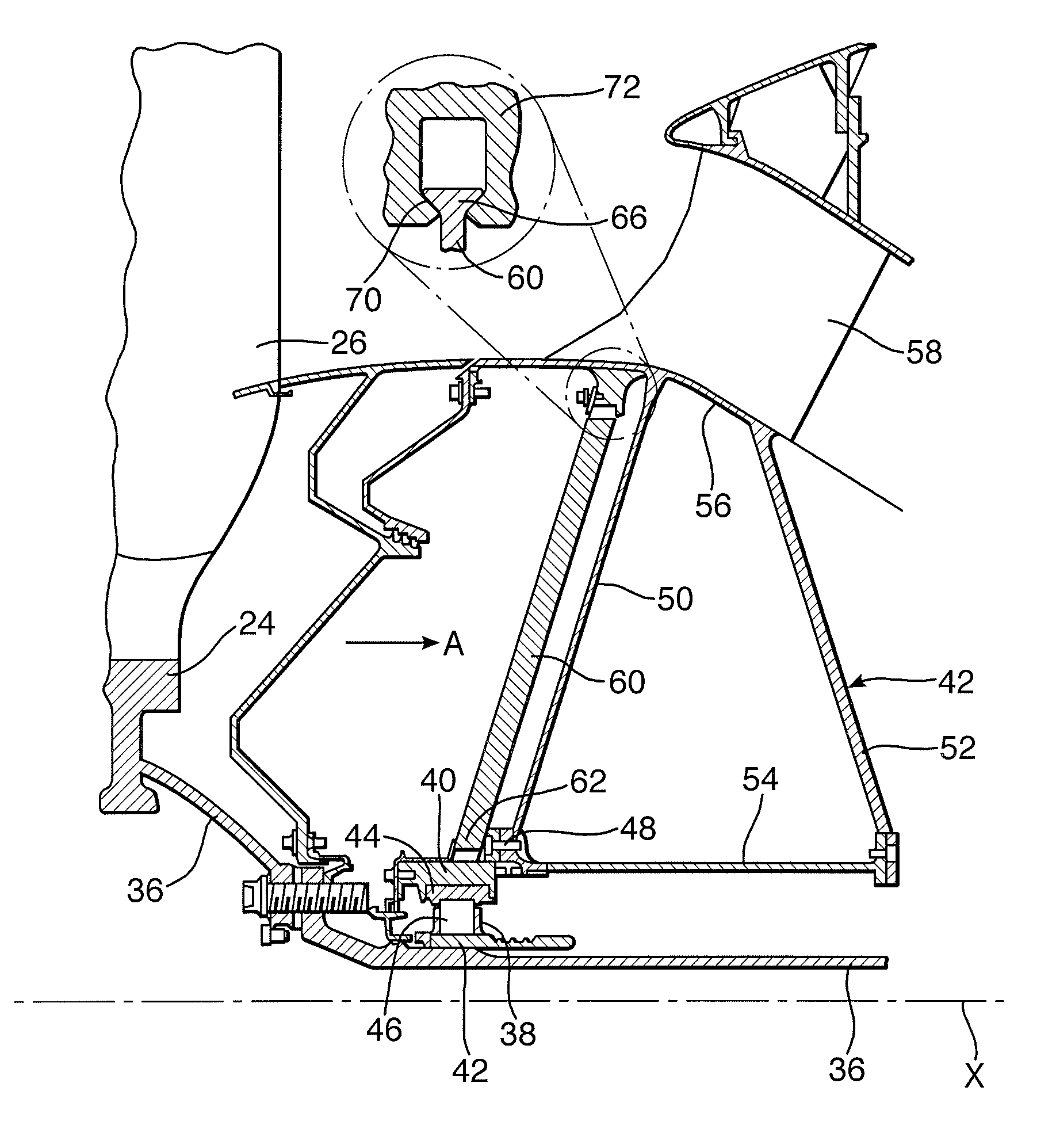
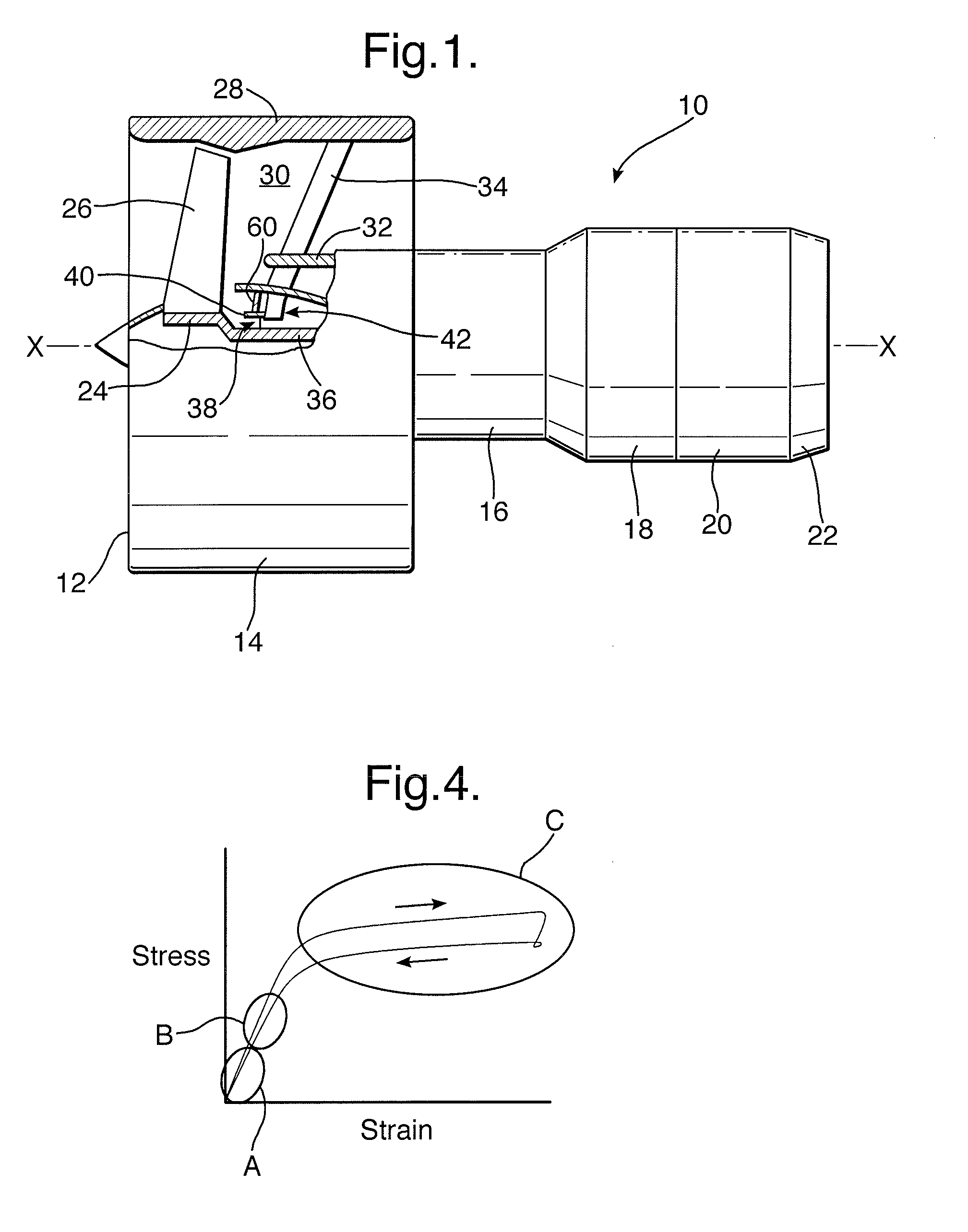
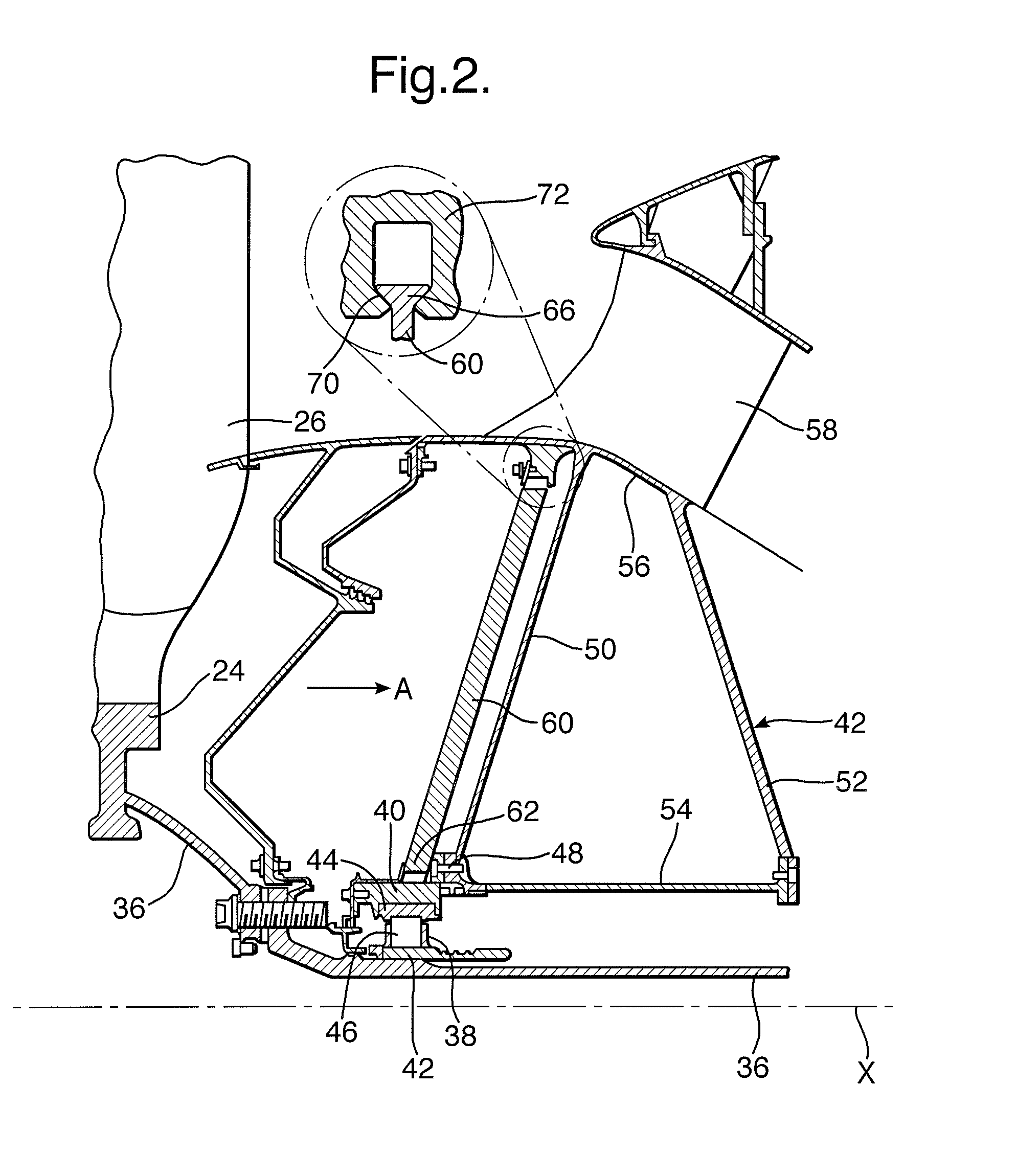
[0030]A turbofan gas turbine engine 10, as shown in FIG. 1, comprises in axial flow series an inlet 12, a fan section 14, a compressor section 16, a combustion section 18, a turbine section 20 and an exhaust 22. The fan section 14 comprises a fan, which includes a fan rotor 24 carrying a plurality of circumferentially spaced radially outwardly extending fan blades 26. The fan rotor 24 and fan blades 26 are surrounded by a fan casing 28 to define a fan duct 30. The fan casing 28 is supported from a core engine casing 32 by a plurality of circumferentially spaced radially extending fan outlet guide vanes 34. The compressor section 16 comprises an intermediate-pressure compressor (not shown) and a high-pressure compressor (not shown) or a high-pressure compressor (not shown). The turbine section 20 comprises a high-pressure turbine (not shown), an intermediate-pressure turbine (not shown) and a low-pressure turbine (not shown) or a high-pressure turbine (not shown) and a low-pressure t...


PUM


Abstract

In a turbofan gas turbine engine, a fan shaft is rotatably mounted and radially supported by a bearing in a bearing support structure supported from a fixed engine structure by radially frangible bolts and radially extending spokes. The radially inner ends of the radially extending spokes are mounted on a common member that engages the bearing support structure. The radially outer ends of the radially extending spokes are mounted on a fixed engine structure located radially outwardly of the bearing support structure. The radially extending spokes are held in tension and include a super elastic material to exert a radially inward restoring force on the bearing support structure, subsequent to any radial excursion of at least part of the fan shaft relative to an engine rotational axis (X) following any fracture of the frangible bolts.

Description

CROSS-REFERENCE TO RELATED APPLICATION[0001]This application is entitled to the benefit of British Patent Application No. GB 0624363.8 filed on Dec. 6, 2006.FIELD OF THE INVENTION[0002]The present invention relates to turbofan gas turbine engines, generally and in particular, to a turbofan gas turbine engine with a fan shaft frangible connection.BACKGROUND OF THE INVENTION[0003]Turbofan gas turbine engines are used for powering aircraft and comprise a relatively large diameter fan, which is driven by a core engine. The fan is vulnerable to damage as a result of foreign objects entering the turbofan gas turbine engine. In most cases, the fan is sufficiently robust to withstand the effects of such foreign object ingestion without suffering major damage and is able to continue operating, although, perhaps, at reduced efficiency.[0004]On very rare occasions, the fan may be damaged to such an extent that parts of one or more of the fan blades that make up the fan are lost. This usually n...

Claims


Application Information

Patent Timeline
Patent Type & Authority Patents(United States)
IPC IPC(8): F01D25/00F01D25/16
CPCF01D21/045F01D21/08F01D25/164F04D27/0292F04D29/056F16C27/04F05B2260/3011F05D2250/70F05D2300/505F16C19/26F16C2360/23F02C7/06F04D29/05F16C27/00
Inventor WEBSTER, JOHN RICHARDUDALL, KENNETH FRANKLINTOWNSEND, JAMES MARTIN
Owner ROLLS ROYCE PLC
Why Eureka
Try Eureka