
High-capacity PTC heater

a heater and positive temperature technology, applied in the field of high-capacity ptc heaters, can solve the problems of high fire danger, energy waste and environmental pollution, and the heating is not performed immediately after the engine, and achieve the effects of improving heat transfer efficiency, increasing heat exchange area, and facilitating assembly and fabrication

Active Publication Date: 2013-04-30
HYUNDAI MOTOR CO LTD +2
View PDF22 Cites 2 Cited by
  • Summary
  • Abstract
  • Description
  • Claims
  • Application Information

AI Technical Summary

Benefits of technology

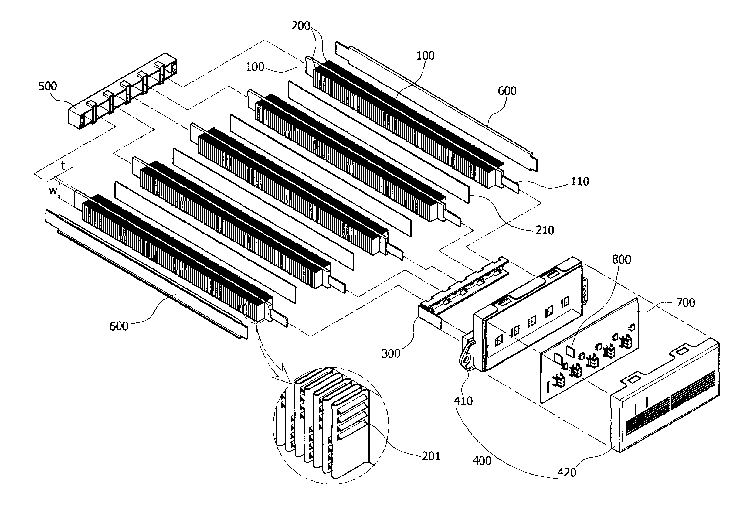
[0017]Various aspects of the present invention are directed to provide a high-capacity Positive Temperature Coefficient (PTC) heater, in which heat-radiating fins are attached to either side of PTC rods by bonding to further improve heat transfer efficiency from the PTC rods to the heat-radiating fins, the heat-radiating fins bonded to the heat-radiating fins exclude a fixing device for fixing the heat-radiating fins in position to facilitate assembly and fabrication, the heat-radiating fins are formed as louver fins to increase a heat exchange area with the air, thereby improving overall heat exchange efficiency, and the thickness of the PTC rods is reduced and the width of the PTC rods and of the heat-radiating fins is increased to improve heat transfer and exchange efficiency, so that high-capacity output can be obtained.

Problems solved by technology

However, in the winter season, heating is not performed immediately after the engine is started since it takes some time until the engine is heated after being started.
This idling of the engine causes energy waste and environmental pollution.
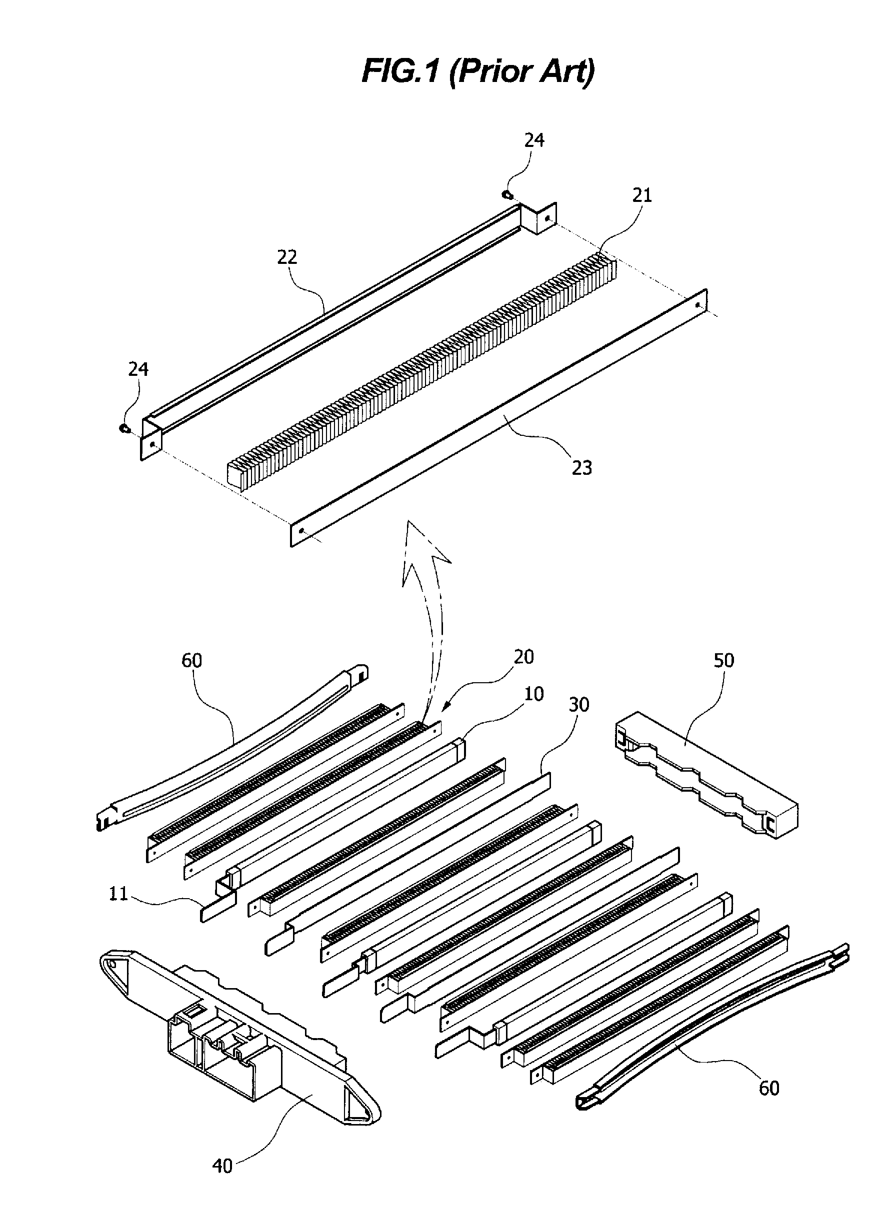
A conventional heater using a heating coil effectively performs the heating due to high heat generation, but has problems such as high fire danger and frequent repair and replacement of parts due to short lifetime of the heating coil.
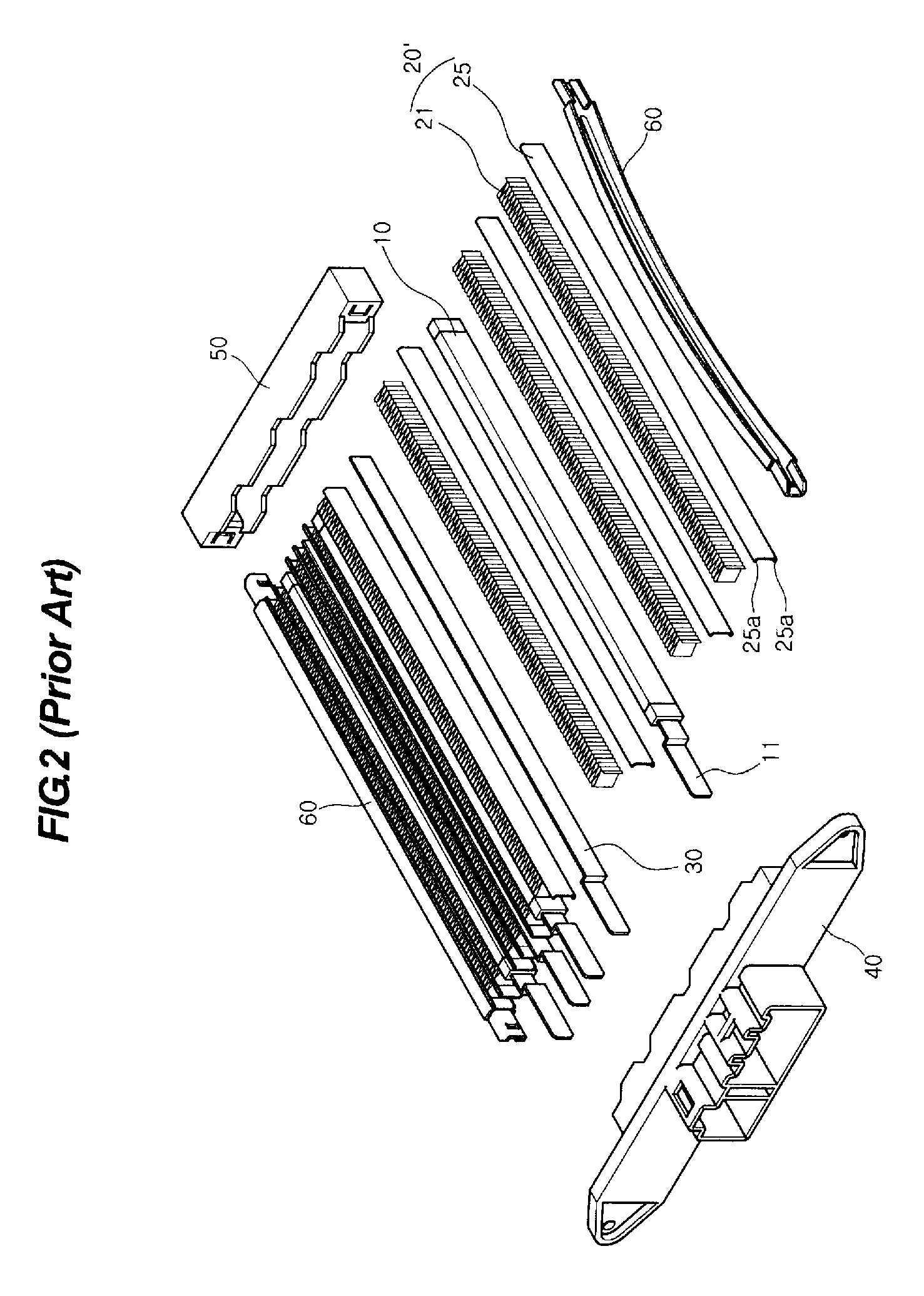
Although this structure can be regarded to be simpler than that of FIG. 1, the heat-radiating fin module 20′ still suffers from a complicated manufacturing process and a large number of parts.
Therefore, this type of heater is not suitable for the high-capacity PTC heater in terms of efficiency.

Method used


Image

  • High-capacity PTC heater
  • High-capacity PTC heater
  • High-capacity PTC heater

Examples


Embodiment Construction

[0031]Reference will now be made in detail to various embodiments of the present invention(s), examples of which are illustrated in the accompanying drawings and described below. While the invention(s) will be described in conjunction with exemplary embodiments, it will be understood that present description is not intended to limit the invention(s) to those exemplary embodiments. On the contrary, the invention(s) is / are intended to cover not only the exemplary embodiments, but also various alternatives, modifications, equivalents and other embodiments, which may be included within the spirit and scope of the invention as defined by the appended claims.

[0032]FIG. 3 is a front elevational view illustrating the structure of a high-capacity PTC heater according to an exemplary embodiment of the present invention, and FIG. 4 is a schematic exploded perspective view illustrating the structure of the high-capacity PTC heater shown in FIG. 4.

[0033]Referring to FIGS. 3 and 4, the high-capac...


PUM


Abstract

A high-capacity positive temperature coefficient heater, may include a plurality of positive temperature coefficient rods, wherein each of the positive temperature coefficient rods has a built-in positive temperature coefficient element that generates heat when electric power is supplied thereto, a plurality of heat-radiating fins attached to either side of the positive temperature coefficient rods along a longitudinal direction thereof, an upper housing coupled to one ends of the positive temperature coefficient rods, and a lower housing coupled to the other ends of the positive temperature coefficient rods, wherein the heat radiating fins are bonded to the positive temperature coefficient rods by heat conductive adhesive.

Description

CROSS REFERENCE TO RELATED APPLICATION[0001]The present application claims priority to Korean Patent Application Number 10-2008-0114251 filed on Nov. 17, 2008, the entire contents of which application is incorporated herein for all purposes by this reference.BACKGROUND OF THE INVENTION[0002]1. Field of the Invention[0003]The present invention relates to a high-capacity Positive Temperature Coefficient (PTC) heater. More particularly, the present invention relates to a high-capacity PTC heater, in which heat-radiating fins are attached to either side of PTC rods by bonding to further improve heat transfer efficiency from the PTC rods to the heat-radiating fins, the heat-radiating fins bonded to the heat-radiating fins exclude a fixing device for fixing the heat-radiating fins in position to facilitate assembly and fabrication, the heat-radiating fins are formed as louver fins to increase a heat exchange area with the air, thereby improving overall heat exchange efficiency, and the th...

Claims


Application Information

Patent Timeline
Patent Type & Authority Patents(United States)
IPC IPC(8): H05B3/06
CPCH05B3/50H05B2203/02B60H1/00B60H1/08B60H1/32
Inventor OH, MAN JUJUN, DUCK CHAESUNG, TAE SOO
Owner HYUNDAI MOTOR CO LTD
Learn More