Air conditioning arrangement for an aircraft with a plurality of climate zones that may be individually temperature-controlled

a climate zone and climate control technology, applied in the direction of refrigeration machines, energy-saving board measures, refrigeration safety arrangements, etc., can solve the problems of not executing an ideal stirling process of the practicable stirling engine, and achieve the effect of reducing noise development, improving efficiency, and improving efficiency

Inactive Publication Date: 2013-05-07
AIRBUS OPERATIONS GMBH
View PDF19 Cites 9 Cited by
  • Summary
  • Abstract
  • Description
  • Claims
  • Application Information

AI Technical Summary

Benefits of technology

[0014]Combined heat and power engines, such as the Stirling engine in particular, make it possible to cool an air flow in addition to heating it. For the basic temperature control, of the air supply this property allows the temperature requirement of individual, in particular comparatively small climate zones, to be ignored and thus the basic temperature of the air supply to be set at a level which potentially lies above the required temperature level for the climate zones not considered. By allocation of at least one respective combined neat and power engine to the sub-branching system of each climate zone not considered, the air supply may be cooled or heated in these sub-branching systems below or above the basic level, as required. The climate zones considered for determining the required basic temperature of the air supply may also be restricted to those which are of primary importance for example owing to their extent and/or use. In particular for example, the cockpit region and those cabin regions in which air passengers stay may be considered. A limitation of t...

Problems solved by technology

It is understood that a practical Stirling engine does not execute an ideal Stirl...

Method used


Image

  • Air conditioning arrangement for an aircraft with a plurality of climate zones that may be individually temperature-controlled
  • Air conditioning arrangement for an aircraft with a plurality of climate zones that may be individually temperature-controlled
  • Air conditioning arrangement for an aircraft with a plurality of climate zones that may be individually temperature-controlled

Examples


Embodiment Construction

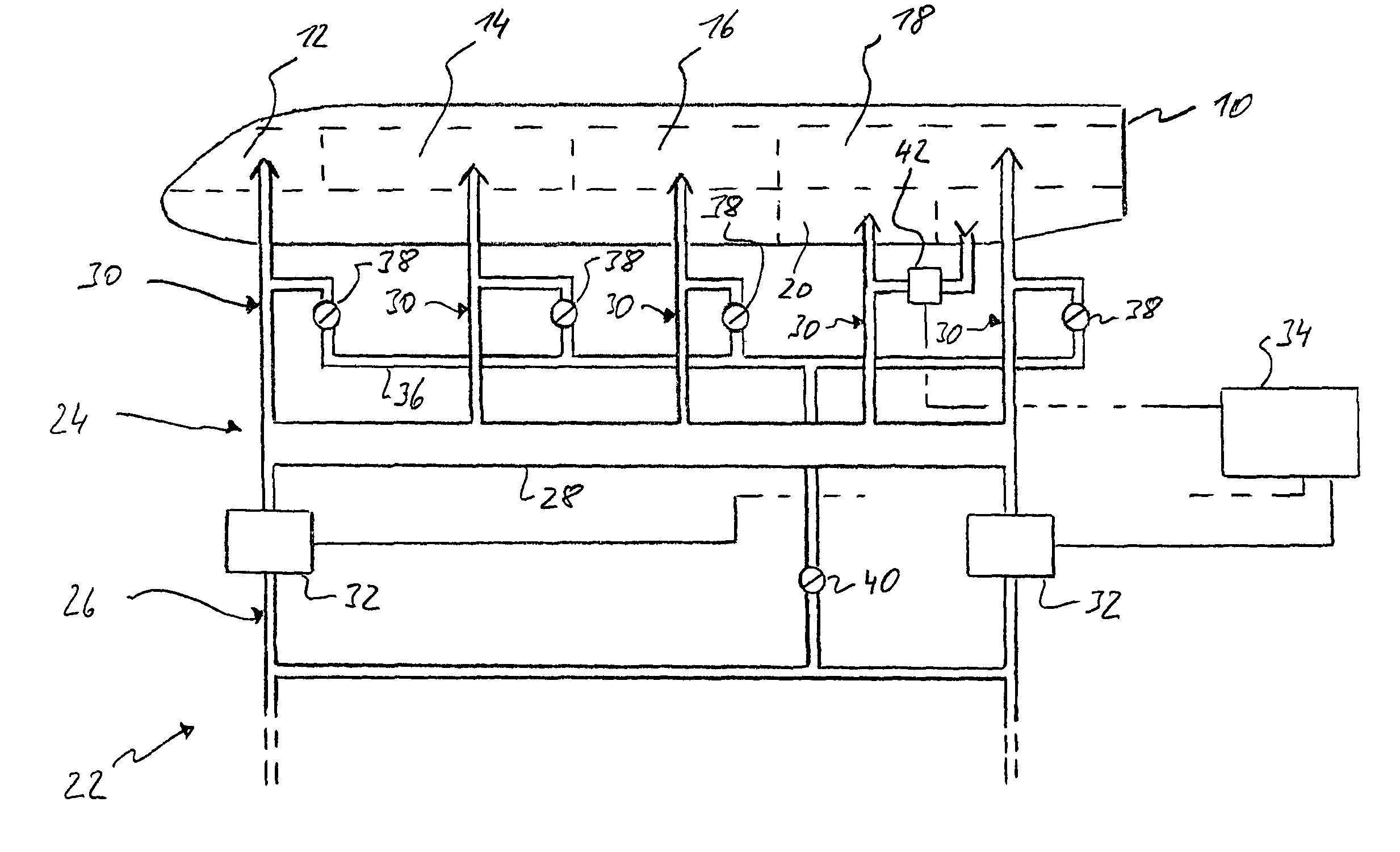
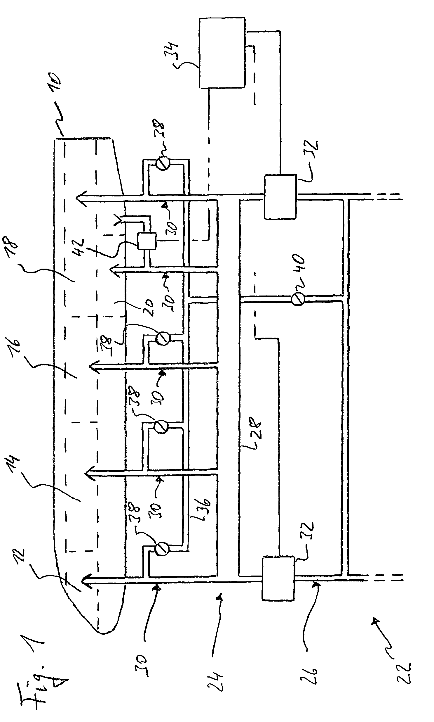
[0025]In FIG. 1, a plurality of climate zones 12, 14, 16, 18, 20 that may be individually temperature-controlled, is formed in the interior of a highly schematic aircraft 10. A total of five such climate zones are formed in the example of FIG. 1. Climate zone 12 comprises the aircraft cockpit, while climate zones 14, 16, 18 contain various passenger regions of the aircraft cabin. Climate zone 20 is a cabin region which is used only for temporary detention of persons, in particular a rest room for the cabin crew. It is understood that this useful division of the various climate zones is only exemplary and a different configuration of the climate zones may be selected at any time. It is also understood that the sketched arrangement of the climate zones in FIG. 1 is based only a schematic representation and is not necessarily true to reality.

[0026]An air conditioning arrangement 22, which supplies the climate zones with a temperature-controlled air supply via an air supply feed path sy...


PUM


Abstract

An air conditioning arrangement for an aircraft with a plurality of climate zones that may be individually temperature-controlled includes a main branching system having an air supply feed path system with a mixing chamber and a plurality of sub-branching systems branching from the mixing chamber and leading to one of the climate zones in each case. Basic temperature control means are used for controlling the temperature of the air supply in the mixing chamber. Individual temperature-control means are used on the other hand for individually controlling the temperature of the air supply in each of the sub-branching systems as a function of a desired temperature value of the respective climate zone. Basic temperature control of the air supply in the mixing chamber preferably takes place independently of a temperature requirement of the climate zone with associated combined heat and power engine.

Description

CROSS-REFERENCE TO RELATED APPLICATIONS[0001]This application claims priority to International Application No. PCT / EP2007 / 000225, filed on Jan. 11, 2007, and German Application No. 10 2006 005 037.1, filed on Feb. 3, 2006.TECHNICAL FIELD[0002]The invention relates in particular to the air conditioning of aircraft interiors, but may also be transferred to the air conditioning of any other desired premises per se.BACKGROUND[0003]In modern commercial aircraft, the aircraft interior is usually divided into a plurality of climate zones which can each be temperature-controlled separately and individually. Not only is it thus possible to keep the temperature in a specific interior region more constant, because temperature control of a smaller spatial region is always easier than temperate control of a larger spatial region, it is also thus possible to adjust different temperatures in different spatial regions, so the comfort-related expectations of cabin crew and / or air passengers may be i...

Claims


Application Information

Patent Timeline
IPC IPC(8): B64D13/02
CPCB64D13/06B64D2013/0655Y02T50/56Y02T50/50
Inventor CENTOFANTE, NICO
Owner AIRBUS OPERATIONS GMBH
Why Eureka
Try Eureka