Rotor for motor

a technology for rotating wheels and motors, applied in the direction of manufacturing stator/rotor bodies, magnetic circuit rotating parts, magnetic circuit shape/form/construction, etc., can solve the problems of disengagement or undesired rotation of magnets, affecting the stability of magnets, and affecting the engagement stability. , to achieve the effect of improving the stability of engaging

Inactive Publication Date: 2013-05-07
SUNONWEALTH ELECTRIC MACHINE IND
View PDF17 Cites 15 Cited by
  • Summary
  • Abstract
  • Description
  • Claims
  • Application Information

AI Technical Summary

Benefits of technology

[0010]An objective of the present invention is to provide a rotor for a motor that provides enhanced engaging stability between the shaft and the plastic magnet.
[0011]Another objective of the present invention is to provide a rotor for a motor that can be assembled more easily.
[0012]A further objective of the present invention is to provide a rotor for a motor that has less complicated structure.

Problems solved by technology

However, the magnet 52 is liable to break.
However, the adhesive is liable to lose its adhesiveness due to deterioration, resulting in disengagement or undesired rotation of the magnet 52 from or relative to the shaft 51.
However, the rotor 6 solves the disadvantages of the rotor 5 at the cost of a complicated structure, resulting in inconvenience in assembly.
However, the fixing seats 73 for sandwiching and fixing the magnet 72 cause limitation in the compact design of the rotor.
Namely, the rotor 7 is still complicated and inconvenient to assemble.
Although enhanced engaging stability is provided between the shaft 81 and the plastic magnet 82, the outer periphery of the rotor 8 must be processed to form the positioning portion 811, leading to inconvenience in manufacturing of the rotor 8.
Furthermore, the engaging area provided by the positioning portion 811 is limited.
Namely, the resultant engaging stability between the plastic magnet 82 and the shaft 81 is still insufficient.
However, the engaging member 92 is liable to deform due to overheating during high speed rotation of the rotor 9, resulting in poor rotational balance as well as disengagement between the magnetic hub 91, engaging member 92, and shaft 93.
Thus, the overall engaging stability of the rotor 9 is still insufficient.

Method used


Image

  • Rotor for motor
  • Rotor for motor
  • Rotor for motor

Examples


first embodiment

[0036]With reference to FIGS. 6 and 7, a rotor 1 for a motor of a first embodiment according to the present invention includes a shaft 11, a coupling member 12, and a plastic magnet 13. The shaft 11 and the coupling member 12 are tightly engaged with each other. The plastic magnet 13 integrally envelops the shaft 11 and the coupling member 12. The coupling member 12 prevents the plastic magnet 13 from disengaging from the shaft 11.

[0037]The shaft 11 can be a rod made of stainless steel. The shaft 11 includes an outer periphery having an engaging portion 111. The engaging portion 111 has an outer diameter D1 perpendicular to an axial direction of the shaft 11.

[0038]The coupling member 12 can be a metal ring that is less hard than the shaft 11. As an example, the coupling member 12 can be an annular member made of copper such that the shaft 11 is less likely to be damaged by the coupling member 12 when the coupling member 12 is engaged with the shaft 11 by tight coupling. Furthermore,...

second embodiment

[0042]By the above technical feature, the coupling member 22 of the rotor 2 of the second embodiment has non-circular cross sections due to provision of the positioning portion 222. Thus, the plastic magnet 23 engages with the positioning portion 222 when the plastic magnet 23 integrally envelops the coupling member 22 and the intermediate portion of the shaft 21. Thus, the coupling member 22 not only prevents the plastic magnet 23 from moving axially or disengaging from the shaft 21, but also prevents the plastic magnet 23 from rotating relatively to the shaft 21, providing further enhanced positioning effect in the axial direction.

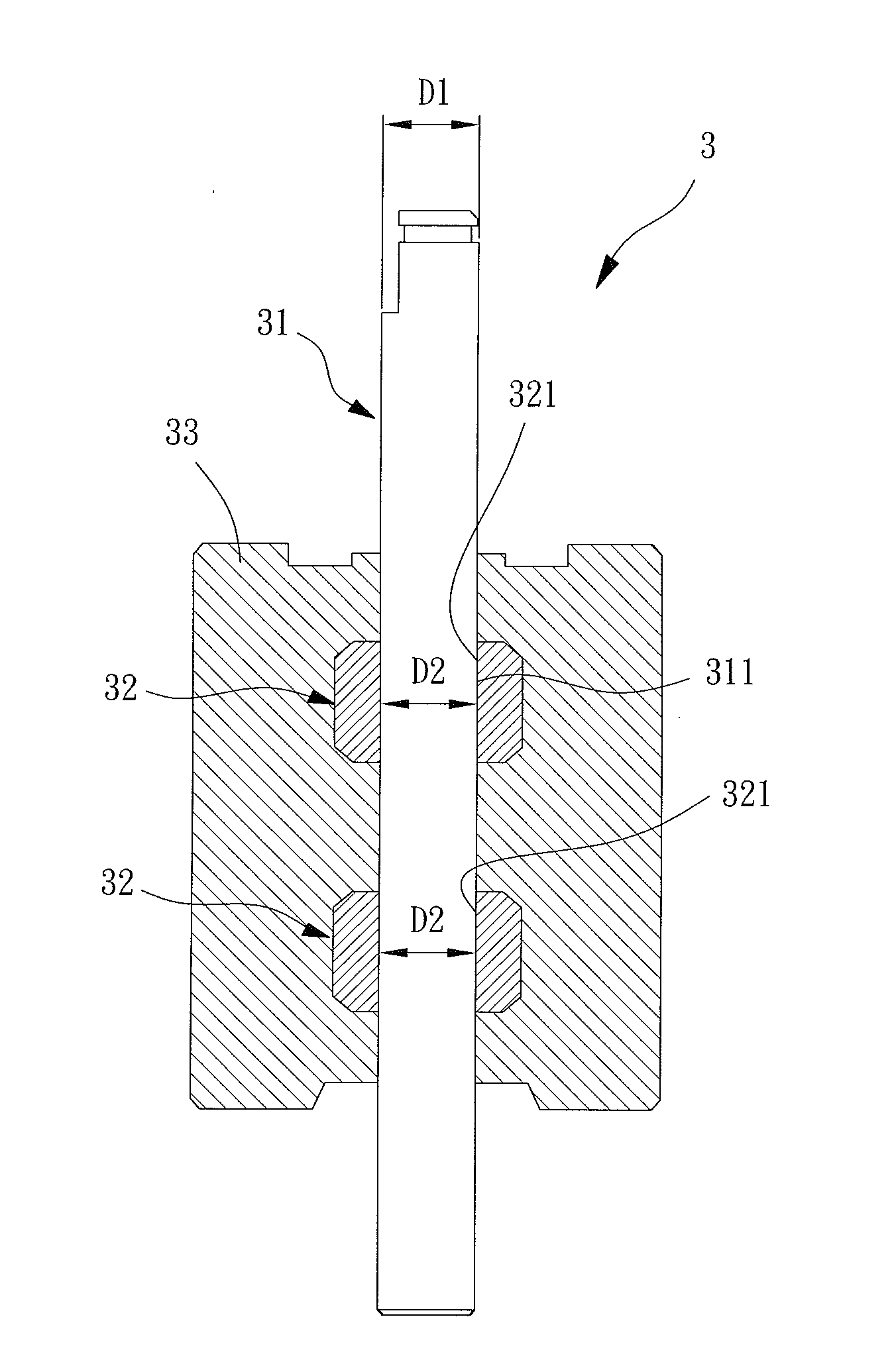
[0043]With reference to FIGS. 12 and 13, similar to the rotor 1 of the first embodiment, a rotor 3 for a motor of a third embodiment according to the present invention includes a shaft 31 with an engaging portion 311, a coupling member 32 with an engaging hole 321, and a plastic magnet 33. The difference between the rotor 3 of the third embodiment and th...


PUM


Abstract

A rotor for a motor includes a shaft having an outer periphery with an engaging portion. At least one coupling member includes an engaging hole. The shaft extends through the engaging hole of the at least one coupling member. The at least one coupling member is engaged with the engaging portion of the shaft by tight coupling. A plastic magnet envelops the shaft and the at least one coupling member by injection molding. The at least one coupling member prevents the plastic magnet from disengaging from the shaft, providing enhanced engaging effect while reducing structural complexity and enhancing assembling convenience.

Description

BACKGROUND OF THE INVENTION[0001]1. Field of the Invention[0002]The present invention relates to a rotor for a motor and, more particularly, to a rotor for a motor of an inner rotor type.[0003]2. Description of the Related Art[0004]Motors generally include an outer rotor type and an inner rotor type that is superior to the outer rotor type in rotational stability. Thus, inner rotor type motors are superior to outer rotor type motors in fulfilling the needs of heat dissipation in the design trends of high speed, integration of functions, and miniaturization.[0005]There is a plurality of conventional inner rotor type motors. FIG. 1 shows a conventional rotor 5 for an inner rotor type motor. The rotor 5 includes a shaft 51 and a magnet 52. The magnet 52 includes a central axial hole 521 through which the shaft 51 extends. The shaft 51 can be in tight coupling with the central axial hole 521 of the magnet 52. However, the magnet 52 is liable to break. In another approach, the shaft 51 i...

Claims


Application Information

Patent Timeline
Patent Type & Authority Patents(United States)
IPC IPC(8): H02K1/27H02K15/03
CPCH02K1/28H02K1/30H02K15/12H02K1/2733
Inventor HORNG, ALEXCHUANG, HUNG JENSHAN, DUO-NIAN
Owner SUNONWEALTH ELECTRIC MACHINE IND
Why Eureka
Try Eureka