
System and method for recovery of packets in overlay networks

a packet recovery and overlay network technology, applied in the field of network systems, can solve the problems of packet loss, increased latency of conventional packet recovery protocols, and high price of overlay network us

Active Publication Date: 2013-05-07
LTN GLOBAL COMM
View PDF17 Cites 17 Cited by
  • Summary
  • Abstract
  • Description
  • Claims
  • Application Information

AI Technical Summary

Problems solved by technology

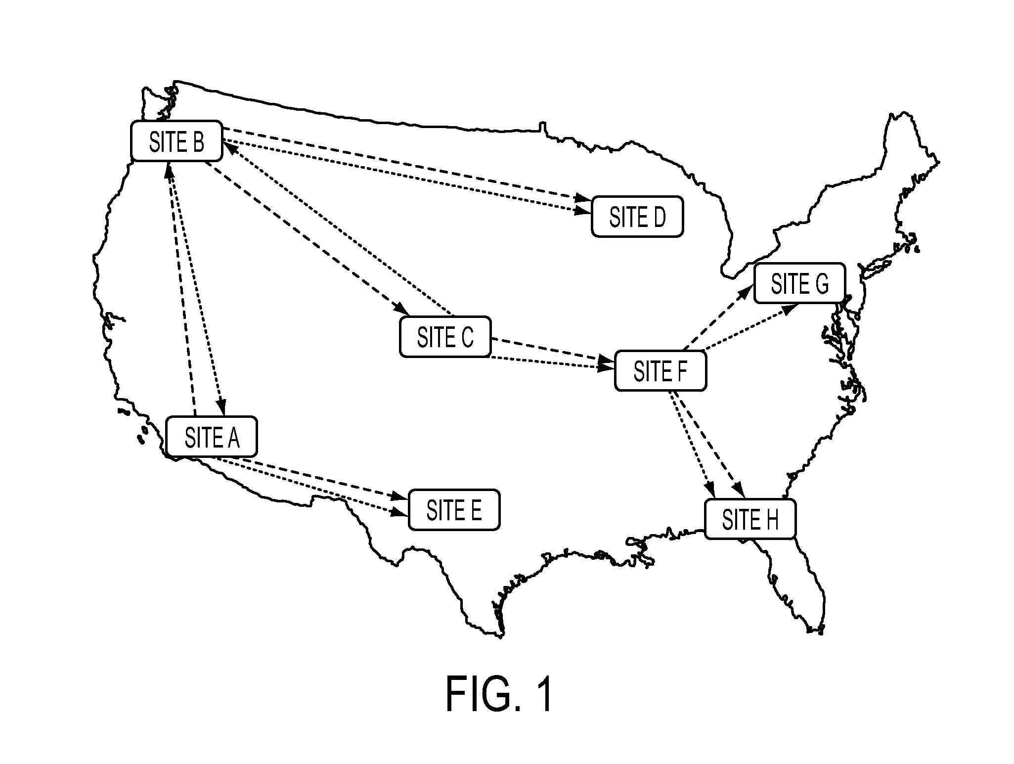
Usually, the usage of overlay networks may come with a price, for example, in added latency that is incurred due to longer paths created by overlay routing, and by the need to process the messages in the application level by every overlay node on the path.
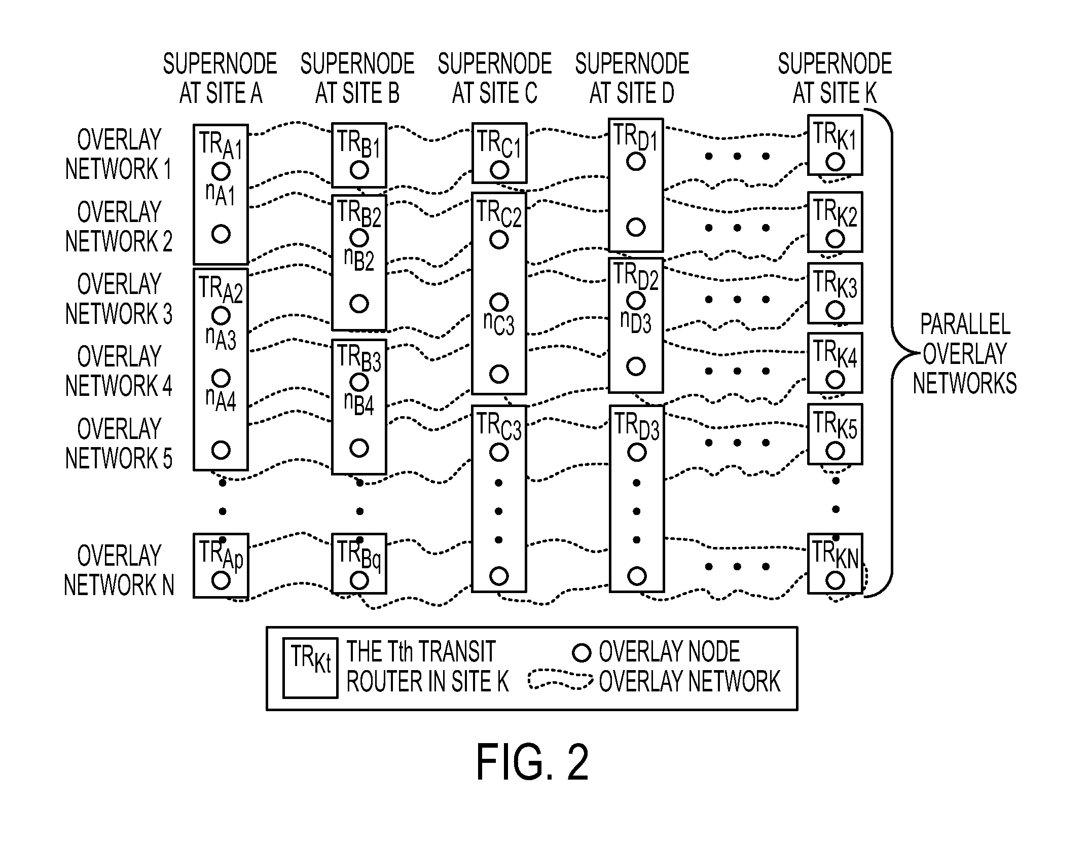
More specifically, in the disclosed MOON, intermediate overlay nodes handle reliability and congestion control only for the links to their immediate neighbors and do not keep any state for individual flows in the system.
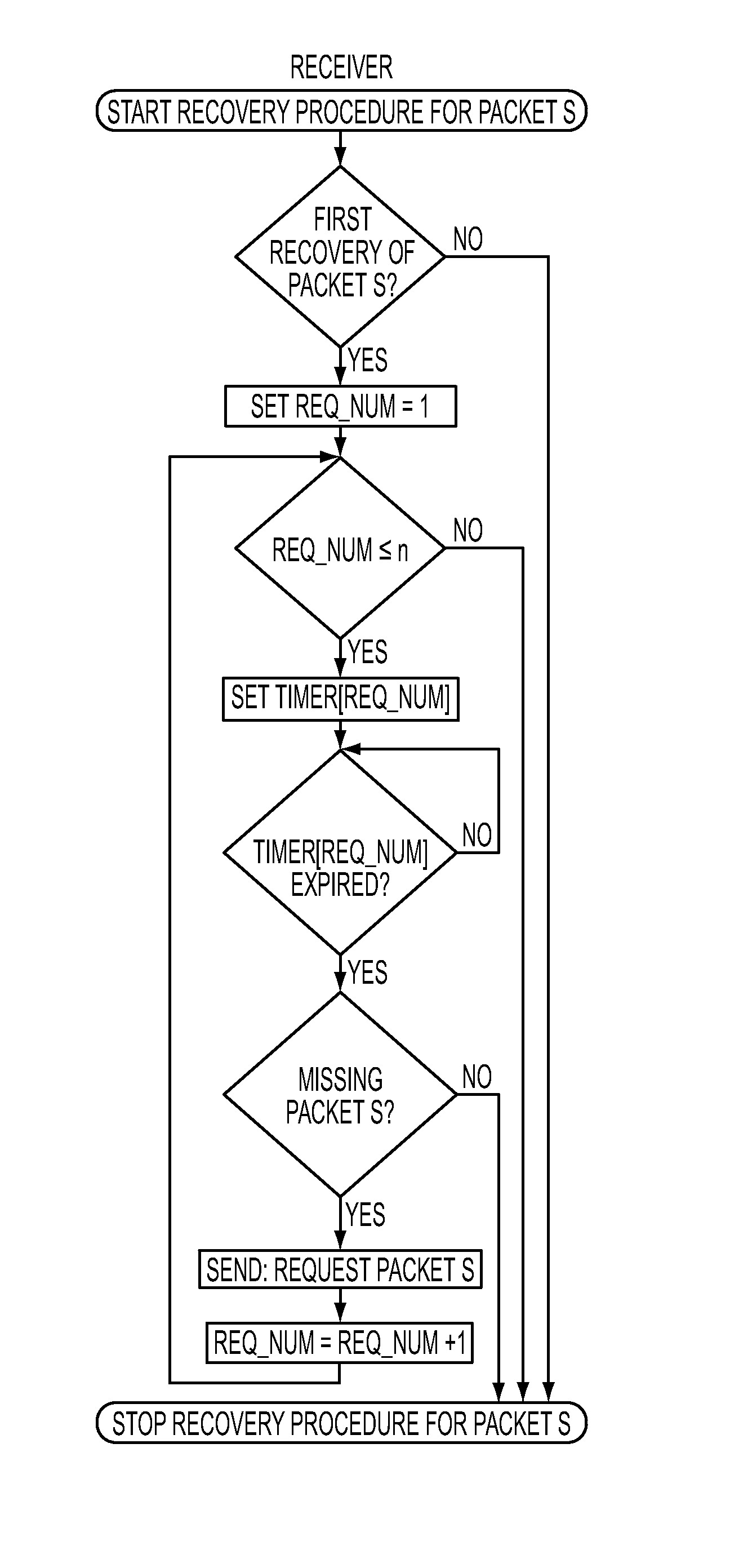
Thus, conventional packet recovery protocols incur additional latency because the lost packets could not be delivered until packet losses are first detected, requests for retransmissions of the lost packets are sent, and the retransmission of the packets are received.
Packets transmitted over network links may be lost because of signal corruption in transit, congestion along the link, or buffer overflows in queues along the path.

Method used


Image

  • System and method for recovery of packets in overlay networks
  • System and method for recovery of packets in overlay networks
  • System and method for recovery of packets in overlay networks

Examples


Embodiment Construction

[0030]One embodiment of the present invention is implemented with application-level overlay networks comprising a plurality of parallel overlay networks that are applied over an underlying network of nodes, for example an IP network, such as the Internet. The present invention is described herein according to the following definitions:

DEFINITIONS

[0031]A process is an algorithm or method executed in a processing unit.

[0032]A state information is any information that a processes receives for performing a task or produces by performing a task.

[0033]A global state information is any state information that is shared with processes in more than one site.

[0034]A real-time process is a process that is executed to complete tasks before a specified deadline.

[0035]A processing unit is the basic unit of computation provided by a CPU that can execute independent JO and computation tasks. For example, in a multi-core CPU it would be a core, in a single-core CPU it would be the CPU itself Hardware...


PUM


Abstract

The present invention relates to a packet recovery method for packets communicated between sender and receiver nodes of an overlay network that runs over an underlying IP network. The present invention executes a packet recovery process at a receiver node upon satisfaction of a packet recovery condition that is associated with meeting a deadline driven criteria for a transmitted packet. The packet recovery process associates N number of scheduled times with N requests for retransmission of the transmitted packet. At least one of the N scheduled times includes a receiver waiting time. At each N scheduled time, a request for retransmission of the transmitted packet is transmitted to a source node. A packet retransmission process at the sender node is executed upon the first receipt of a request for retransmission of the transmitted packet. In one embodiment, the packet retransmission process retransmits the transmitted packet to the receiver node at M number of scheduled times, where the N and M are non-zero positive integers and at least one of the N or M number of scheduled times is greater than one.

Description

RELATED APPLICATIONS[0001]This non-provisional application incorporates by reference the following provisional applications in their entirety: U.S. Provisional Application No. 61 / 140,065, filed on Dec. 22, 2008; U.S. Non-provisional application Ser. No. 12 / 506,725, filed on Jul. 21, 2009, U.S. Non-provisional application Ser. No. 12 / 537,582, filed on Aug. 7, 2009; Provisional Application Ser. No. 61 / 082,270, filed Jul. 21, 2008; Provisional Application Ser. No. 61 / 086,987, filed Aug. 7, 2008; Provisional Application Ser. No. 61 / 664,459, filed Apr. 3, 2009.FIELD OF THE INVENTION[0002]The present invention generally relates to the field of network systems and more particularly to protocols and systems for the recovery of transmitted packets in such networks.BACKGROUND OF THE INVENTION[0003]An overlay network is a computer network that is built on top of another network. Nodes in the overlay can be thought of as being connected by virtual or logical links, each of which corresponds to ...

Claims


Application Information

Patent Timeline
Patent Type & Authority Patents(United States)
IPC IPC(8): G08C15/00G06C25/02
CPCH04L45/04H04L49/557H04L45/64H04L67/104G01R31/08
Inventor AMIR, YAIRSTANTON, JONATHANLANE, JOHN WILLIAMSCHULTZ, JOHN LANE
Owner LTN GLOBAL COMM
Learn More