Syntactic inferential motion planning method for robotic systems

a robotic system and inferential motion technology, applied in the direction of manipulators, electric digital data processing, instruments, etc., can solve the problems of inflexible behaviour or inability to adapt to any change in the particular system they are designed for, and the movement is seldom so straightforward

Active Publication Date: 2007-01-04
THERMO CRS
View PDF11 Cites 83 Cited by
  • Summary
  • Abstract
  • Description
  • Claims
  • Application Information

AI Technical Summary

Benefits of technology

[0033] e) where the shortest distance is less than or equal to the distance limit, assigning the robot to the nearest location.
[0034] In a further embodi

Problems solved by technology

In real applications, however, motion is seldom so straightforward.
the robot entering an invalid geometry that would, for example, spill the contents of the payload or cause some other unwanted effect.
Due to such infinite number of possibilities, upon encountering a singularity, the result would be unexpected and unsafe movement of the device, which should be avoided.
Although coded scripts specific to a particular application are relatively simple to design, they also have the disadvantage of being inflexible in behaviour or not adaptable to any change to the particular systems they are designed for.
It is, therefore, difficult to have such a system take advantage of fort

Method used


Image

  • Syntactic inferential motion planning method for robotic systems
  • Syntactic inferential motion planning method for robotic systems
  • Syntactic inferential motion planning method for robotic systems

Examples


Embodiment Construction

Definitions

[0053] The following terms are used in the present description and will be assumed to have the following meanings:

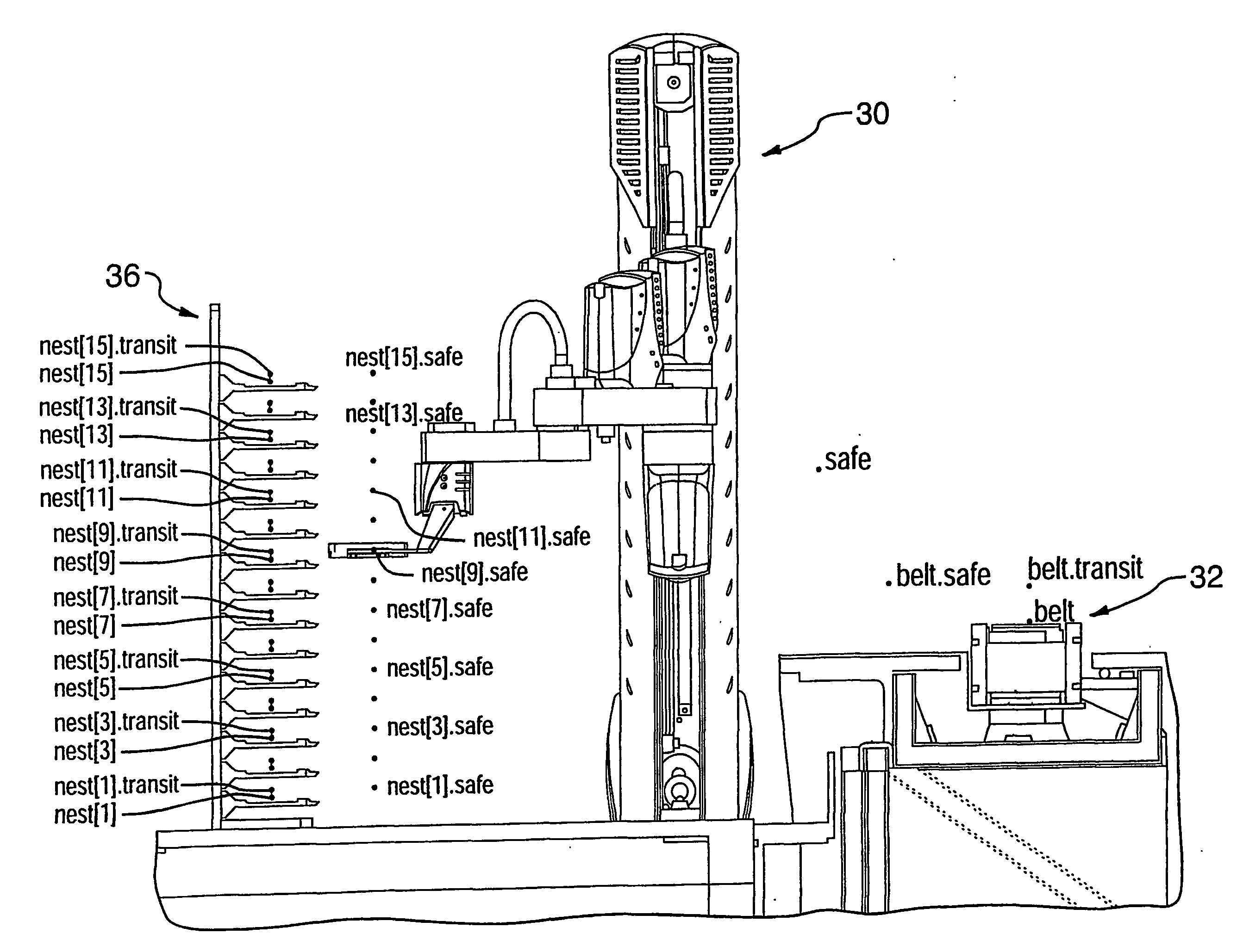
[0054]“Robot end effector”, “robot”, “robotic device”, “mover”: are used to refer to the moving end of a robotic device that perform the desired function. This can include, for example, the grasping end of a robotic arm. The assignee of the present invention, Thermo CRS Ltd., manufactures several types of such movers and examples are provided at www.thermo.com (the contents of which are incorporated herein by reference).

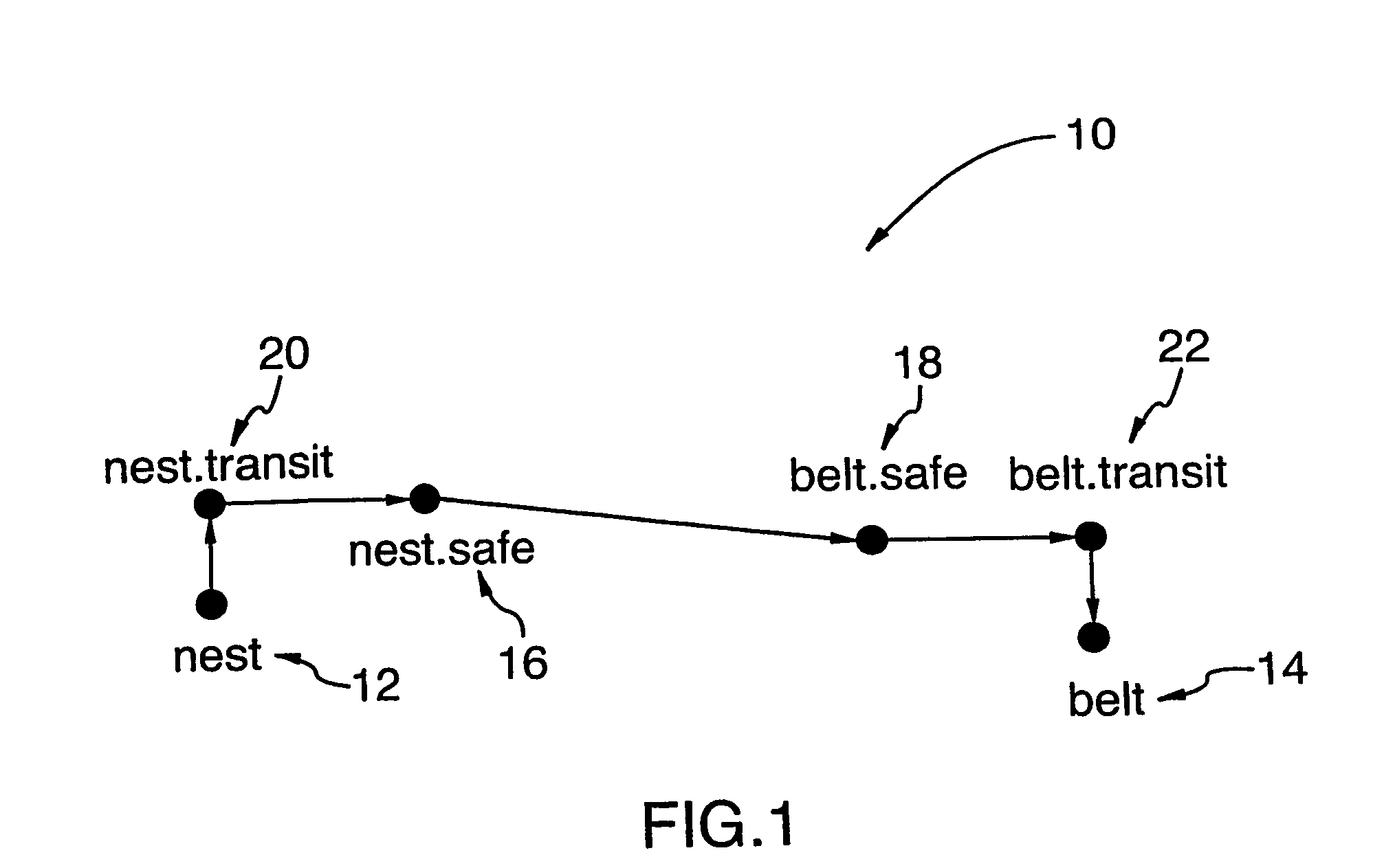
[0055]“Terminal points”: refers to the points, or locations, where the robot end effector a actually interacts with objects. For example, in cases, as described further below, where a robotic arm is used to move an object from a conveyor belt to a nest in a carousel used to house the objects, the terminal points would consist of “belt” and “nest”.

[0056]“Safe points”: refers to pseudo-destinations where the robot end effector can be safely ...


PUM


Abstract

A method and system for planning and optimizing the movement of a robotic device comprises establishing a plurality of spatial locations where the device can possibly be positioned and establishing rule sets for constraining movement of the robotic device between the locations. Once a start and end point have been determined, the method of the invention calculates all possible routes for the device to move, via the established locations and following the constraints of the rule sets. The calculated routes are then compared to a criteria, such as minimizing time, and an optimum route, meeting the desired criteria is determined. The calculated routes may also be cached for future access. The invention also provides for an error recovery method for allowing a robotic device to recover should it encounter an error.

Description

CROSS REFERENCE TO PRIOR APPLICATIONS [0001] This application claims priority from U.S. application No. 60 / 443,839, filed on Jan. 31, 2003.BACKGROUND OF THE INVENTION [0002] 1) Field of the Invention [0003] The present invention relates to operational planning systems for robotic devices and particularly to methods of controlling and optimizing the movement of such devices using syntax based algorithms. The invention also provides an error recovery method for robotic devices. [0004] 2) Description of the Prior Art [0005] Robots are exceedingly adept at moving in straight lines between precisely specified points. In real applications, however, motion is seldom so straightforward. Typical applications require the end effector of the robot to move through a series of programmed points to reach a pick-up point, grasp a payload at the pick-up point, then move through another series of points to a drop-off point, etc. [0006] In the sequence of movements executed by the robot's effector, c...

Claims


Application Information

Patent Timeline
IPC IPC(8): G06F7/00B25J9/16
CPCB25J9/163G06Q10/047B25J9/1666
Inventor MCCRACKIN, DANIEL CURTISJOHNSON, STEPHEN WAYNE
Owner THERMO CRS
Why Eureka
Try Eureka