Launch and recovery system for unmanned aerial vehicles

Inactive Publication Date: 2005-01-27
ADVANCED AEROSPACE TECH
View PDF79 Cites 84 Cited by
  • Summary
  • Abstract
  • Description
  • Claims
  • Application Information

AI Technical Summary

Benefits of technology

[0031] It is a further object of the invention to have a recovery system that can recover aircraft at a higher altitude to avoid ground fog or a lower altitude to be under the cloud cover.
[0032

Problems solved by technology

However this prior art discloses a very complicated system with a launching parachute and parachute retainer that gets jettisoned for each recovery cycle which in turn launches a ram-air parachute which holds up a ribbon parachute which acts to capture the UAV.
In this prior art the UAV engaged the ribbon parachute just below the supporting ram-air parachute with very little arrestment distance and thus very high loads.
In this prior art the UAV approaches in the turbulent, blocked flow from the ribbon parachute and the ribbon parachute also causes a very large amount of unnecess

Method used


Image

  • Launch and recovery system for unmanned aerial vehicles
  • Launch and recovery system for unmanned aerial vehicles
  • Launch and recovery system for unmanned aerial vehicles

Examples


Embodiment Construction

[0057] Launch-Preferred

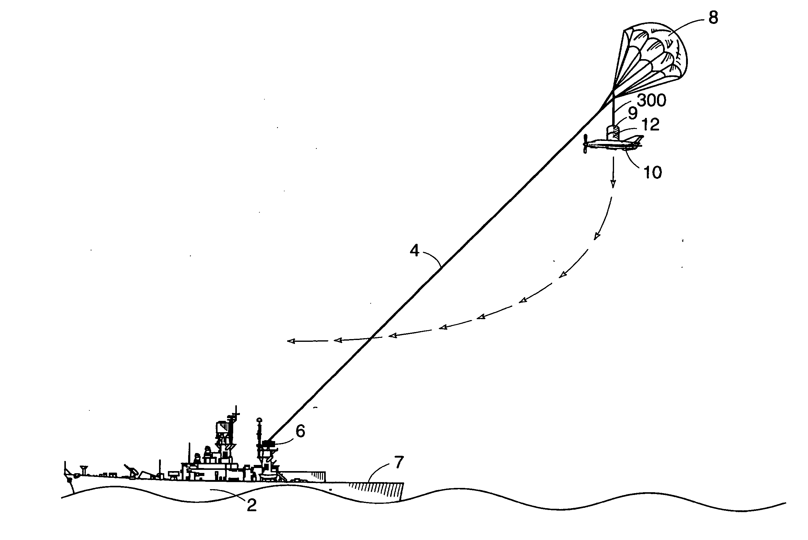
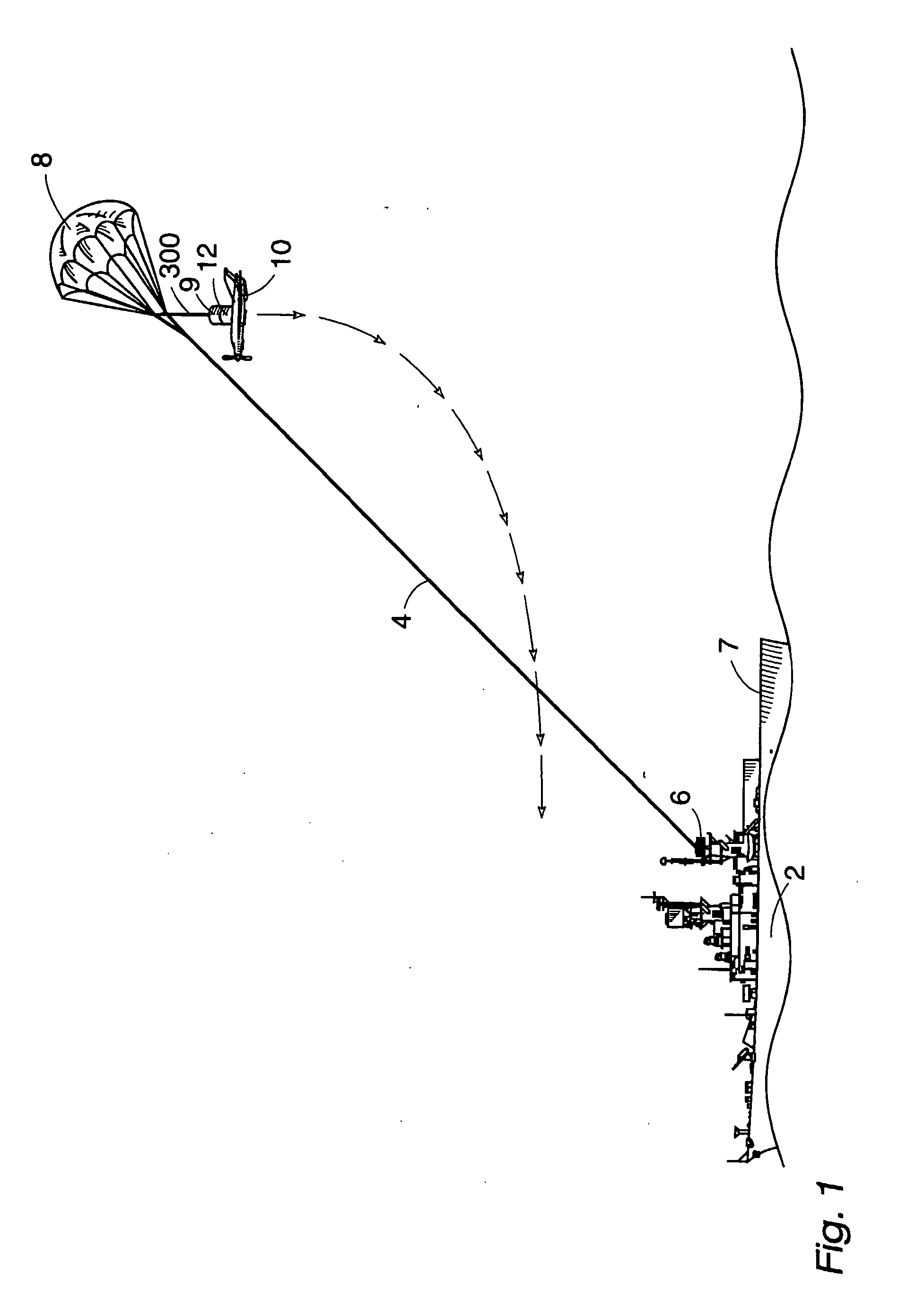
[0058] Referring now by reference numerals to the drawings and first to FIG. 1 one of the preferred embodiments comprises a boat 2, a tow line 4, winch 6, parachute 8, plastic barrel of water as a ballast weight 9, unmanned aerial vehicle (UAV) 10 and release mechanism 12. The launch procedure starts by inflating the parachute 8 which can be done by raising its risers with a pole designed for this purpose which is well known in the art or by having persons hold up the separated riser bundles until the chute inflates in the wind. Because conventional parasailing parachutes need a weight hanging under them to keep them oriented properly after the UAV has been released, a barrel of water 9 or other weight is attached where a tourist would normally be attached to go up parasailing. Use of such a water ballast is well known in the art as a method used for training people to operate parasailing equipment. The release mechanism and structure 12 can be integrated ont...


PUM


Abstract

A method of launching and retrieving a UAV (Unmanned Aerial Vehicle) (10). The preferred method of launch involves carrying the UAV (10) up to altitude using a parasail (8) similar to that used to carry tourists aloft. The UAV is dropped and picks up enough airspeed in the dive to perform a pull-up into level controlled flight. The preferred method of recovery is for the UAV to fly into and latch onto the parasail tow line (4) or cables hanging off the tow line and then be winched back down to the boat (2).

Description

CROSS-REFERENCE TO RELATED APPLICATIONS [0001] This is a divisional application of pending U.S. application Ser. No. 10 / 031,025, which is a national phase application under 35 U.S.C. § 371 of PCT application US00 / 20099, and claims priority of Provisional Application 60 / 145,286, filed Jul. 23, 1999.FIELD OF THE INVENTION [0002] The present invention relates to the methods and mechanisms required to launch and retrieve aircraft from point locations without the use of runways. BACKGROUND OF THE INVENTION [0003] Previously glider aircraft have been towed aloft and then released to fly off on their own and catapults have been used to rapidly accelerate an aircraft up to flying speed in a short distance. Also aircraft have been fitted with tail hooks or other apparatus to try to engage arresting cables or have been flown into nets in order to arrest their forward movement in a short distance. [0004] Prior art U.S. Pat. No. 4,753,400 (Reuter, et al.) comes closest to one of the preferred e...

Claims


Application Information

Patent Timeline
IPC IPC(8): B64C25/68B64C39/02B64D3/00B64F1/02B64F1/04B64F1/10
CPCB64C25/68B64C39/024B64C2201/084B64C2201/104B64C2201/165B64C2201/182B64F1/02B64F1/04B64F1/10B64C2201/205B64D3/00B64U70/70B64U30/10B64U50/13B64U70/30B64U80/84
Inventor MCDONNELL, WILLIAM R.
Owner ADVANCED AEROSPACE TECH
Why Eureka
Try Eureka