Dryer having a lint filter and a cleaning device

Active Publication Date: 2013-05-14
BSH BOSCH & SIEMENS HAUSGERAETE GMBH
View PDF30 Cites 58 Cited by
  • Summary
  • Abstract
  • Description
  • Claims
  • Application Information

AI Technical Summary

Benefits of technology

[0003]The object of the present invention is to specify a generic dryer in which the removal of lint from the lint filter by means of the first cle

Problems solved by technology

However, the space available in the area of the squeegee for accommodating it means that the container is dimensioned relatively small.
On the one hand the accessibility to the accumulation container is restricted during this drying and on the

Method used


Image

  • Dryer having a lint filter and a cleaning device
  • Dryer having a lint filter and a cleaning device
  • Dryer having a lint filter and a cleaning device

Examples


Embodiment Construction

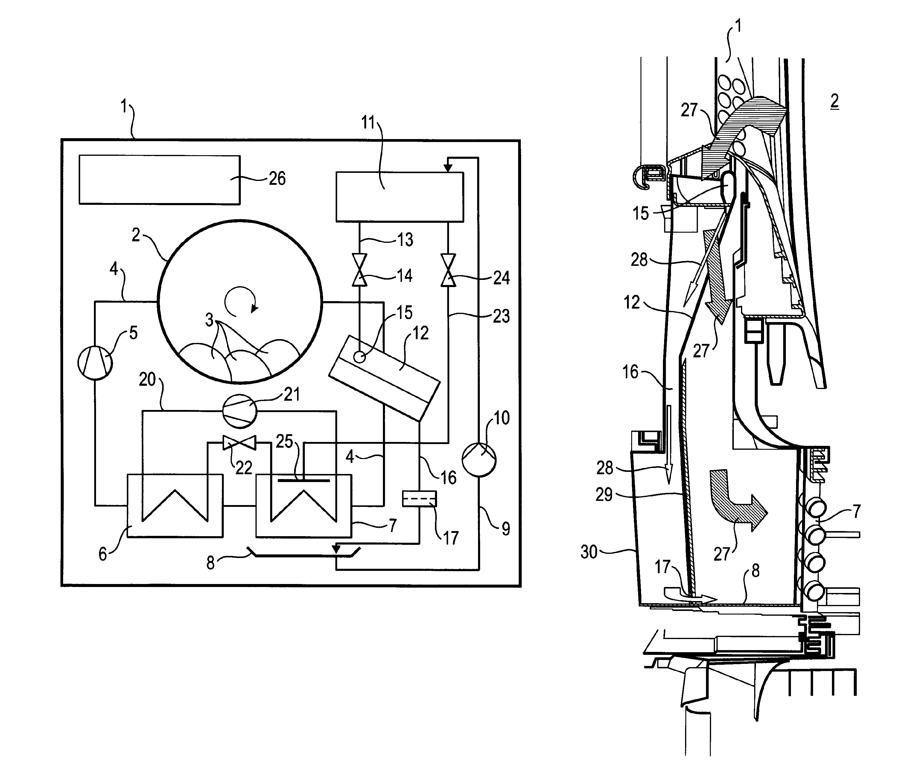
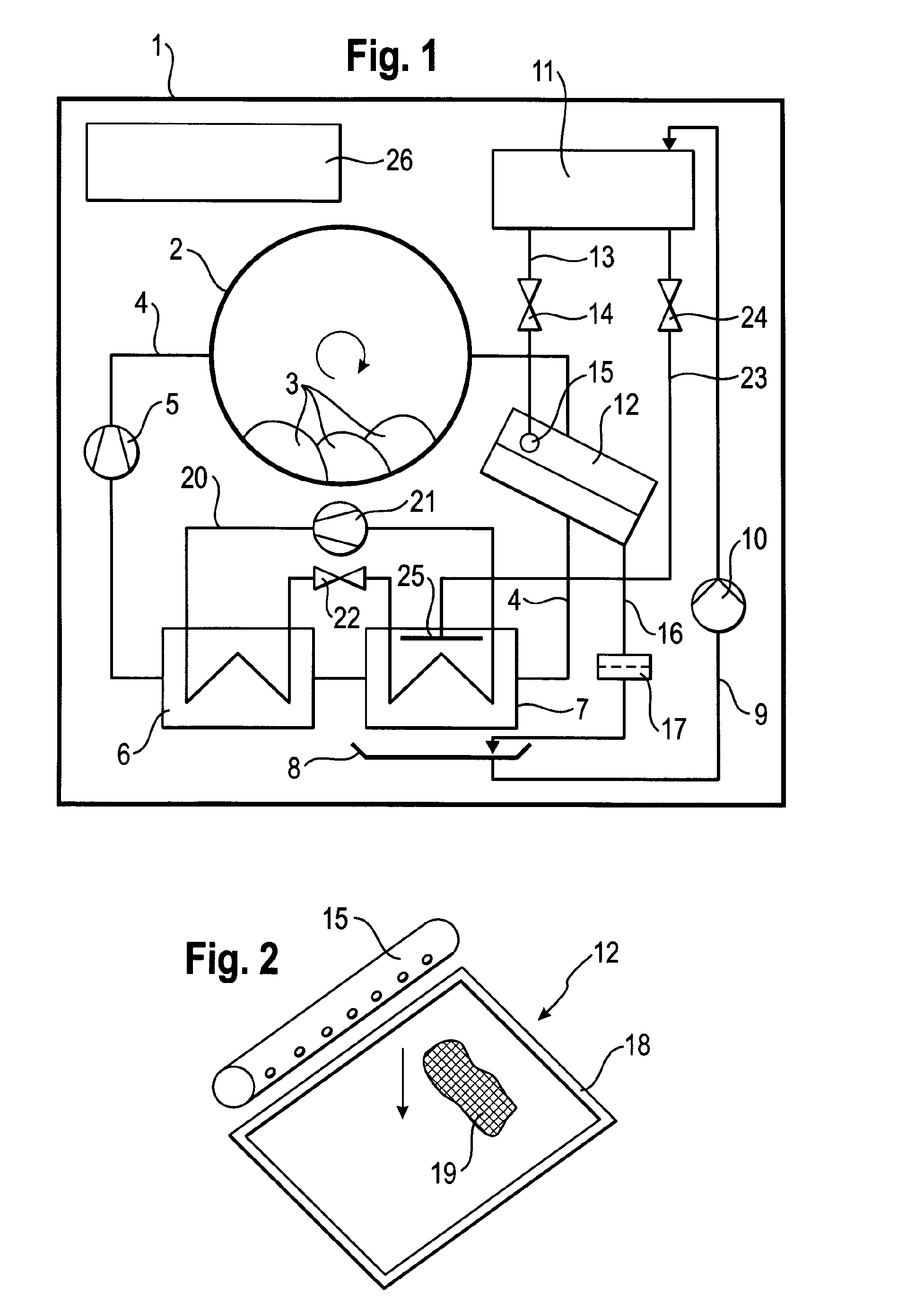
[0019]As shown in FIG. 1, the dryer 1, in this case a tumble dryer 1, comprises a drying chamber 2 designed as a rotatable drum which accepts damp items 3, in this case laundry 3, for drying. For the dryer 1 shown in FIG. 1 a closed process air duct 4 is provided in which a process air flow circulates, driven by a fan 5, which accepts moisture from the laundry 3 and takes it away. In a heat source 6 the process air is heated up before its entry into the drying chamber 2. After the process air heated up in this way, as a result of the rotation of the drying chamber 2, has flowed around laundry 3 falling down in said chamber while taking up moisture therefrom, it leaves the drying chamber 2 and arrives at a heat sink 7. Here it is cooled so that the moisture that it carries with it condenses out, precipitates as condensate in liquid form on the structures of the heat sink 7 and drips down into a collection tray 8 arranged below the heat sink. From the collection tray 8 such condensate...


PUM

PropertyMeasurementUnit
Antimicrobial propertiesaaaaaaaaaa

Abstract

A dryer has a drying chamber to receive damp items and a process air duct to feed process air into and extract process air out of the drying chamber. The process air duct has a heat source and a heat sink to heat the process air before the process air enters the drying chamber and to cool the process air after the process air leaves the drying chamber, respectively. A cleaning device has an accumulator for a liquid; a rinsing line connected to the accumulator; a control organ in the rinsing line; a distributor connected to the rinsing line to distribute the liquid conveyed through the rinsing line on a lint filter and to receive the lint caught by the lint filter; and a drain line to drain the liquid with the received lint away from the lint filter and towards the accumulator.

Description

BACKGROUND OF THE INVENTION[0001]The invention relates to a dryer comprising a drying chamber to accommodate damp items to be dried and an essentially closed process air duct to circulate process air through the drying chamber, said process air duct having a heat source for heating the process air before its entry into the drying chamber and a heat sink for cooling the process air after it leaves the drying chamber, as well as a first lint filter arranged between the drying chamber and the heat source to which a first cleaning device is assigned.[0002]A dryer for drying washing by means of an air flow is known from publications EP 1 788 140 A1, EP 1 788 141 A2 and EP 1 788 142 A2. In the dryer a mesh filter for filtering lint out of the air flow is arranged in the area of the end shield in the process air duct, with said mesh forming a first lint filter. A squeegee is used to wipe off the lint collected in the process air duct by the filter and store it in a container adjacent to th...

Claims


Application Information

Patent Timeline
IPC IPC(8): F26B11/02
CPCD06F58/22
Inventor DITTMER, LOTHARGRUNERT, KLAUSNAWROT, THOMASZIEMANN, ANDREAS
Owner BSH BOSCH & SIEMENS HAUSGERAETE GMBH
Why Eureka
Try Eureka