Eureka AIR delivers breakthrough ideas for toughest innovation challenges, trusted by R&D personnel around the world.

Dryer with heat recovery and method of operation thereof

Inactive Publication Date: 2013-05-14
BSH BOSCH & SIEMENS HAUSGERAETE GMBH
View PDF10 Cites 8 Cited by
  • Summary
  • Abstract
  • Description
  • Claims
  • Application Information

AI Technical Summary

Benefits of technology

The present invention provides a dryer with high energy efficiency. It does not require the pumping out of accumulated condensate or the use of a collection container. The dryer separates out moisture during the drying process, which is a measure of heat recirculation. This allows the dryer to be classified into a better energy consumption class. The maximum amount of moisture separated out is important. The dryer can include a blower to continue running after the drying process and a draft of air to help evaporate any remaining condensate. The drying chamber is sealed off to allow for an undisturbed flow of process air. The heater is regulated based on the degree of drying to save energy. The dryer is more energy efficient than a dryer without heat recovery, and the condensate can be conveyed outside without a collection container.

Problems solved by technology

By comparison, the circulating process air in a condensation dryer can as a rule only be dehumidified at 100% relative humidity at the lowest temperature obtaining in the process air circuit, which limits its capacity for absorbing moisture from the items to be dried and thus restricts the drying process to a certain extent.

Method used


Image

  • Dryer with heat recovery and method of operation thereof
  • Dryer with heat recovery and method of operation thereof
  • Dryer with heat recovery and method of operation thereof

Examples


Embodiment Construction

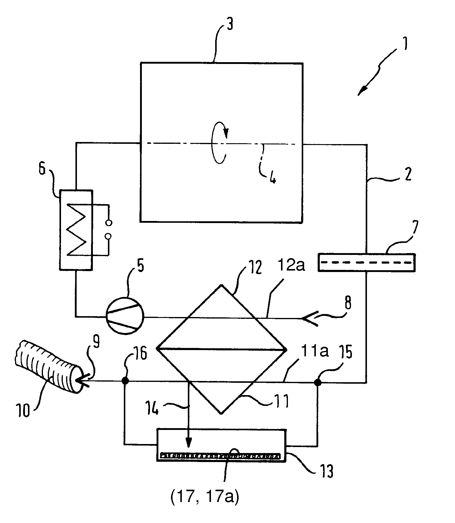
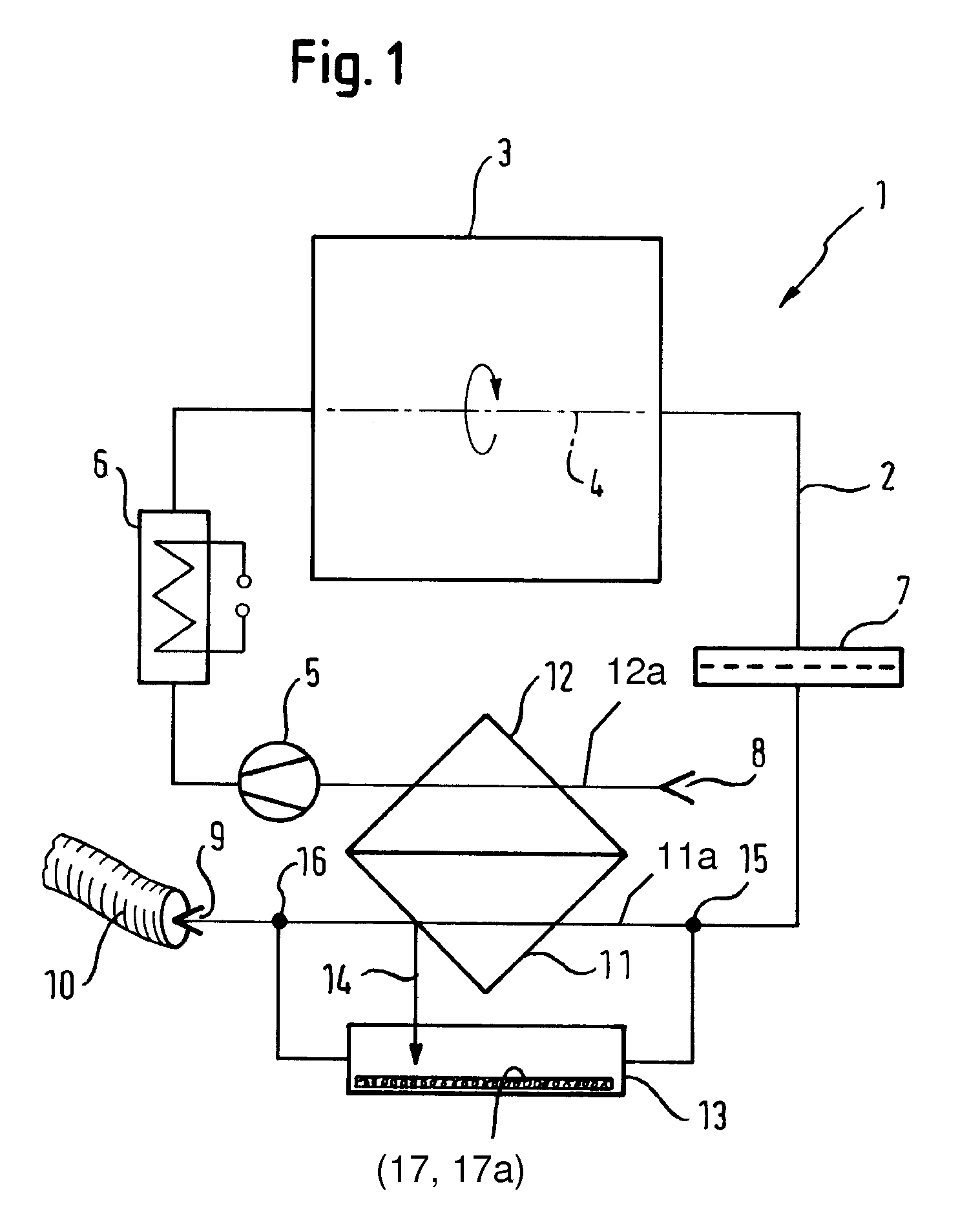
[0031]The dryer 1 represented in FIG. 1 in sketch form has a process air duct 2 and a drying chamber 3, which is a drum 3 rotatable about an axis 4. Process air is directed via a heater 6 through the drum 3 and a lint filter 7 by means of a blower 5.

[0032]The process air is drawn in through an inlet air opening 8 and expelled through an exhaust opening 9. Air directly from an environment of the dryer 1 reaches the inlet air opening 8. Connected to the exhaust opening 9 is an exhaust air hose 10, with which the exhaust air is conveyed from the dryer 1 and out of a room in which it is set up. Also present is a heat exchanger arrangement 11, 12; in this or the corresponding entry channel 12, heat is transferred to the process air drawn in through the inlet air opening 8 from the process air flowing from the drum 3 and the lint filter 7. After passing through the drum 3, the moist, warm process air is cooled down; the process air to be directed to the heater, on the other hand, is prehe...


PUM


Abstract

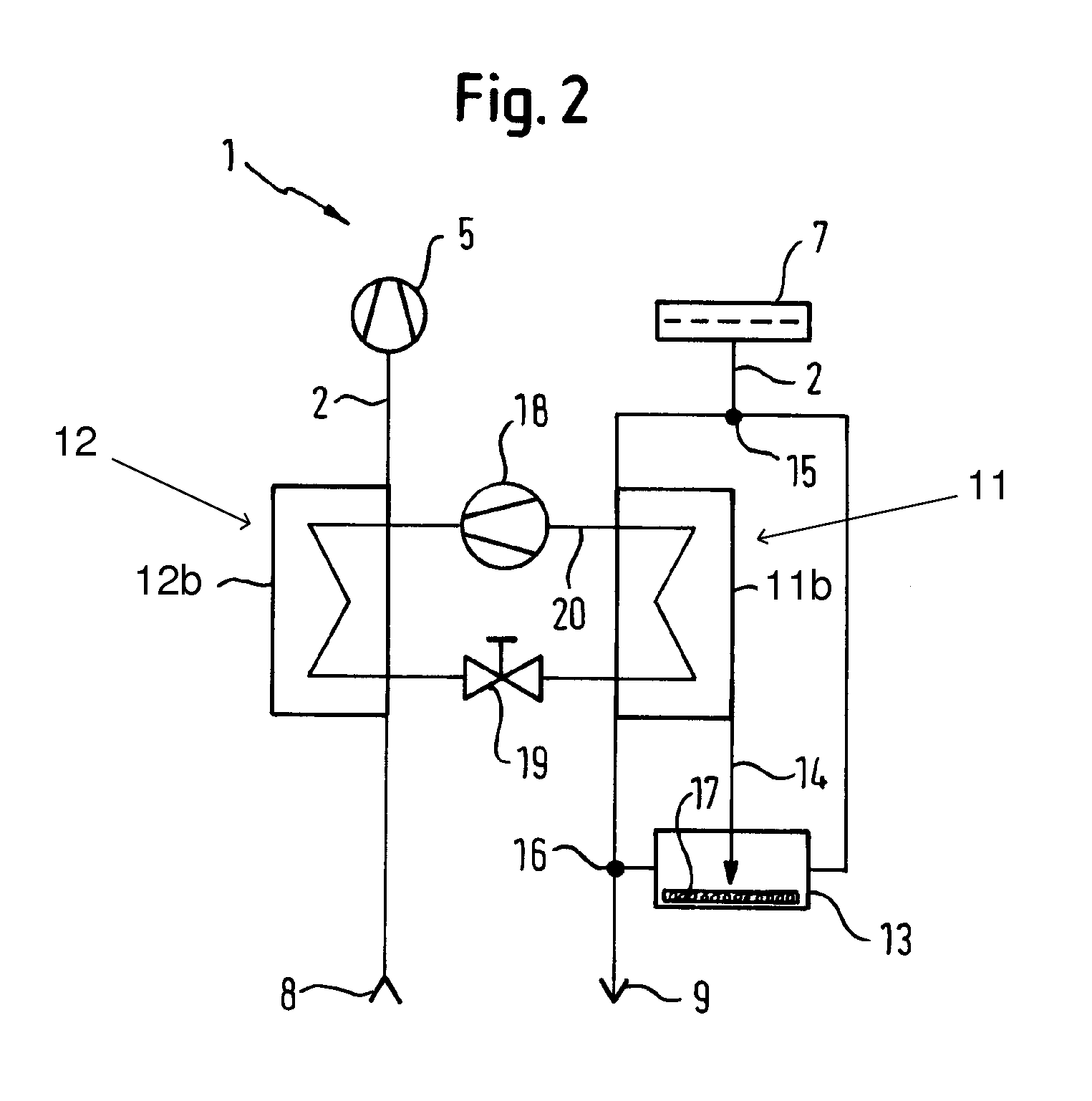
A dryer is provided having a drying chamber for items to be dried and a process air duct in which are located a heater for heating the process air, a blower for driving the process air from the heater through the drying chamber, and a heat exchanger arrangement. Via the heat exchanger arrangement, heat can be withdrawn from the process air flowing away from the drying chamber, and the process air flowing toward the heater can be fed to the heat exchanger. The process air duct is divided into a main duct and a secondary duct, the secondary duct having an evaporator in which condensate that was separated from the process air in the heat exchanger arrangement can be evaporated into the process air flowing therethrough and is connected to the exhaust opening.

Description

BACKGROUND OF THE INVENTION[0001]The invention relates to a dryer with a drying chamber for the items to be dried and a process air duct, in which are located a heater for the heating of process air and a blower for forcing the process air from the heater through the drying chamber and a heat exchanger arrangement, by means of which heat exchanger arrangement heat can be removed from the process air flowing from the drying chamber, and fed to the process air flowing to the heater, where the process air duct has an inlet air opening for drawing in process air from an environment of the dryer and an exhaust opening for expelling process air into the environment of the dryer.[0002]The invention also relates to a method for operating such a dryer.[0003]Such a dryer and such a method follow from DE 30 00 865 A1.[0004]In general a tumble dryer is operated as an exhaust air dryer or a condensation dryer. An exhaust air dryer directs heated air once through the laundry to be dried and conve...

Claims


Application Information

Patent Timeline
IPC IPC(8): F26B3/00F26B19/00F26B21/06
CPCD06F58/24
Inventor STOLZE, ANDREAS
Owner BSH BOSCH & SIEMENS HAUSGERAETE GMBH
Why Eureka
Eureka Blog
Learn More