Supercharge Your Innovation With Domain-Expert AI Agents!

Automatic adjustment of printer drum spacing

a printer and drum technology, applied in the direction of electrographic process, electrographic process apparatus, instruments, etc., can solve the problems of reducing the lifetime of the blanket, reducing the overall machine performance parameters, and reducing the performance of the printing press

Active Publication Date: 2013-05-14
HEWLETT PACKARD DEV CO LP
View PDF8 Cites 5 Cited by
  • Summary
  • Abstract
  • Description
  • Claims
  • Application Information

AI Technical Summary

Benefits of technology

This patent describes a printer that can automatically adjust the space between its printing filters to create the desired pressure and gap without needing operator intervention. This solves the problems with existing printer configurations that require operator adjustment.

Problems solved by technology

This problem also appears in conventional printing presses, and other equipment that need smooth rotation of two cylinders with precisely controlled gap.
An improper first transfer pressure can also degrade overall machine performance parameters by:
(a) Decreasing the blanket lifetime (related to background transfer)
(b) Increasing the amount of ink amount per area unit (dma) and, as a result, ink consumption, reservoir filter lifetime, and fixing
(c) Decreasing the PIP life span
Similarly, an incorrect second transfer pressure (between the ITM drum surface and the blanket on the impression drum) can also decrease blanket life span as well as increase the possibility of paper jams.
The printing blanket and paper thickness both contribute to the second transfer pressure, so that pressure changes may be caused by inconsistent printing blanket thickness.
However, the bearers create a fixed gap which cannot compensate for changes in blanket thickness or other changes.
Therefore the pressure between the plate and blanket may not be optimal, leading to deficiencies in image quality of the print.
This requires high-skilled manual operation, extra materials, and is hard to implement.
However, designing a drum with conical bearers is complicated and increases the hardware costs of the press.
This method requires operator input and is therefore prone to human error.
Furthermore, positioning the print drum for a particular print medium does not account for other factors, such as material tolerances, temperature variations, and so forth.
The process is operator dependent, yielding a difference in pressure between customers, and in many cases is not even performed.
Even when performed, the adjustment process is generally not of high enough precision, so that the best possible performance is not always obtained.
Additionally, since the pressure changes during printing, adjusting the pressure before printing does not ensure that the pressure is optimal during printing.

Method used


Image

  • Automatic adjustment of printer drum spacing
  • Automatic adjustment of printer drum spacing
  • Automatic adjustment of printer drum spacing

Examples


first embodiment

[0057]The printer may be an electrophotographic printer. In a first embodiment, the method adjusts the first transfer pressure, in which case the two drums are the electrostatic (PIP) drum and the ITM drum. In an alternate embodiment, the method adjusts the second transfer pressure, in which case the two drums are the impression drum and the intermediate transfer (ITM) drum.

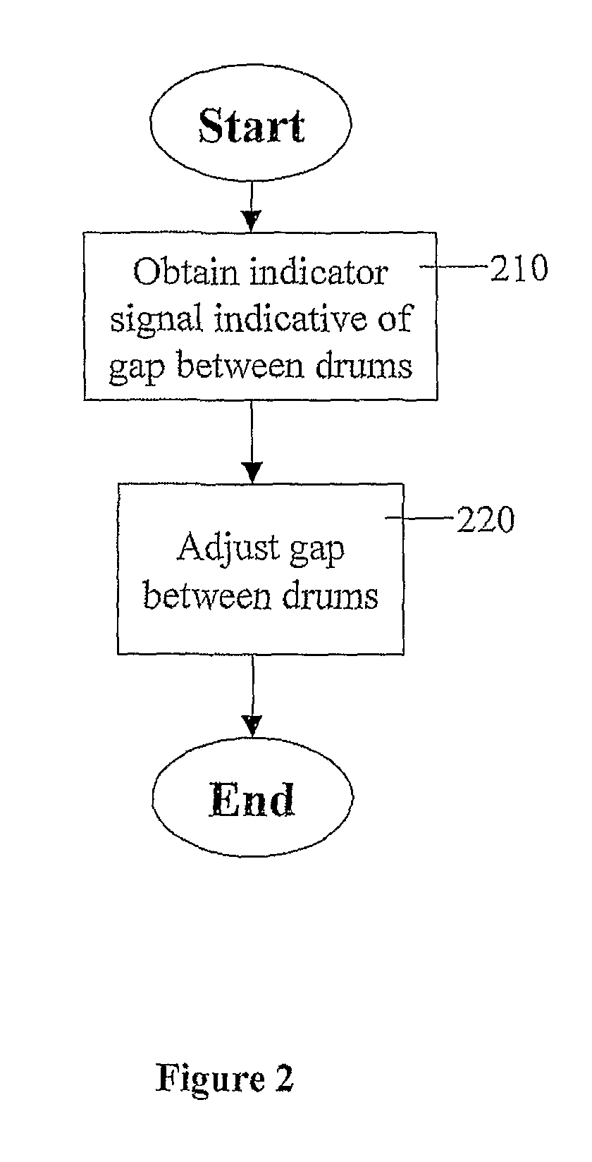
[0058]In step 210, a signal indicative of the pressure (i.e. force) between the two drums is obtained (denoted herein the indicator signal).

[0059]In a first embodiment, the indicator signal is obtained by creating a potential difference between the two drums and measuring the current flow between the drums, as described in more detail below. In a second embodiment, the indicator signal is obtained by measuring the pressure between the two drums by any method known in the art, for example utilizing a strain measurement element (such as a strain gage or load cell) as described below.

[0060]In step 220, the gap betwe...

second embodiment

[0087]Reference is now made to FIG. 9b, which is a simplified illustration of a printer with automatic drum spacing adjustment, according to the present invention. The present embodiment is directed to image transfer from the ITM drum to impression drum 920.1. Strain measurement elements 540.1 and 540.2 (strain gage 540.1 is hidden by impression drum 920.1) provide two input signals (denoted Input 1 and Input 2) to control unit 950. The input signals indicate the strain on the supporting arms of impression drum 920.1. Control unit 950 analyzes the two input signals, and derives a respective control signal (denoted Output 1 and Output 2) for each of the stepping motors, 960.1 and 960.2, in order to adjust the gap between the ITM drum and impression drum 920.1.

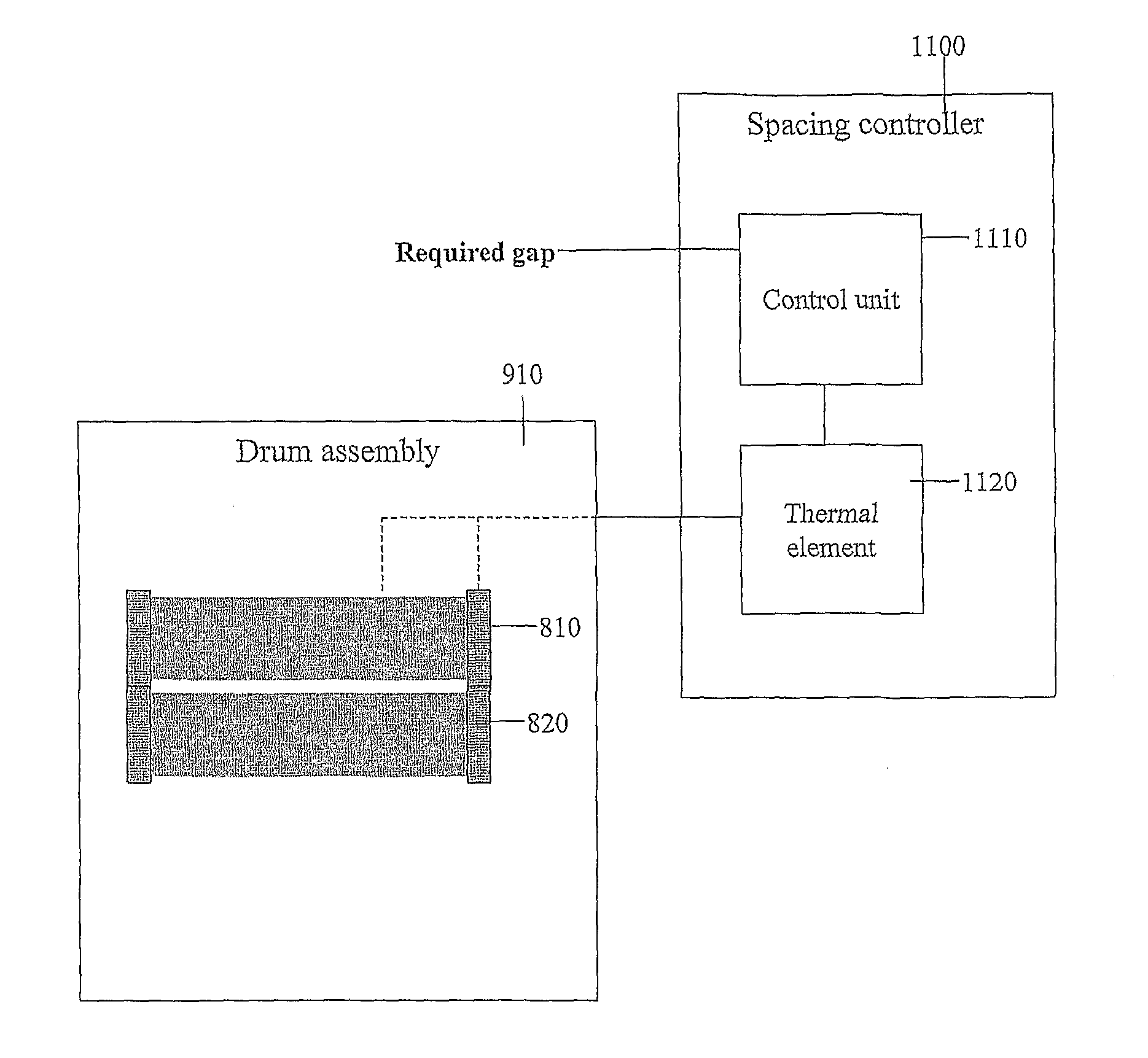
[0088]In a further embodiment, gap adjustment based on current flow is performed by a standalone controller. Reference is now made to FIG. 10, which is a simplified block diagram of a drum spacing controller, according to a firs...


PUM


Abstract

A method is presented for automatically controlling the spacing between printer drums. The printer includes at least two print drums (920.1, 920.2) whose parallel rotation leads to image transfer, either between the drums or onto a printed surface. First the pressure a signal indicative of the pressure between the two print drums is obtained by a measurement unit (930), and then the gap between the drums is automatically adjusted in accordance with the indicator signal by a gap adjuster (940).

Description

FIELD AND BACKGROUND OF THE INVENTION[0001]The present invention relates to automatically adjusting the relative positioning of two printer drums based on a determined level of contact between the drums and, more particularly, but not exclusively to adjusting the positioning of drums of an electrophotographic printer.[0002]Many forms of printing rely on a printing drum whose rotation transfers an image from the drum to a printed substrate. More advanced forms of printing, such as electrophotographic printing, utilize parallel pairs of drums whose joint rotation transfers the image either from one drum to the next, or from one drum to a substrate supported by another drum. Electrophotographic printing machines generally use a two-transfer system of printing in which an electrophotographic image is formed on a first drum (known as the PIP drum) using a laser beam shone onto a photoelectric material, thereby forming an electrostatic image on the photoelectric material. Ink is then draw...

Claims


Application Information

Patent Timeline
Patent Type & Authority Patents(United States)
IPC IPC(8): B41F1/54
CPCG03G15/1605G03G15/50G03G15/00G03G15/16
Inventor LEVANON, DAVIDFRYDMAN, ILANALIOSHIN, YURYLIOR, SHAITAGANSKY, BOAZ
Owner HEWLETT PACKARD DEV CO LP
Features
  • R&D
  • Intellectual Property
  • Life Sciences
  • Materials
  • Tech Scout
  • Unparalleled Data Quality
  • Higher Quality Content
  • 60% Fewer Hallucinations
Learn More