Apparatus and method for mounting of cabinets

a cabinet and mounting device technology, applied in the field of exterior mounting of cabinets, can solve the problems of limited cabinet configuration types, and achieve the effects of minimizing manufacturing and inventory costs, maximizing protection of both cabinets, and minimizing costs and depth profiles of cabinet installations

Active Publication Date: 2013-05-14
WINDSTREAM INTPROP SERVICES LLC +1
View PDF32 Cites 5 Cited by
  • Summary
  • Abstract
  • Description
  • Claims
  • Application Information

AI Technical Summary

Benefits of technology

[0006]In accordance with various illustrative embodiments hereinafter described, the present invention is a device that may be used to mount cabinets that house electronic and electrical devices, such as the types commonly used to provide telecommunication services, in an outdoor environment. The present invention minimizes the costs and the depth profile of cabinet installations, while maximizing protection of both the cabinet and the cable associated with that installation. The present invention also comprises a two-piece pole and mount configuration that allows for the use of one of a variety of mounts that are configured to accommodate different electronics cabinet sizes and configurations to be installed on a single post design, thus minimizing manufacturing and inventory costs.
[0007]The invention can be used in lieu of utility pole with mount kit, H-Frame mounts, pre-cast pads, and site poured pads. The present invention thus reduces the overall cabinet footprint required when placing cabinet apparatus on right of ways (“ROWs”). The present invention also reduces labor costs and site preparation activities.
[0008]The present invention provides a mounting post to raise the electronics cabinet up off the ground, while keeping the overall depth of the total apparatus to a minimum. The present invention raises the electronics cabinet up off the ground by approximately 2 feet, making it easier to work on and less likely to get damaged from ROW mowers. The hollow post design provides for protection of the cabling routed in the interior, and requires less site preparation than other methods, as little to no leveling is required. The elongated slot in the side of the post allows cables to be routed through the post without impingement or abrasion. The top mount design allows for a minimum depth dimension and reduces man-hours and equipment required because the 14″ diameter post will fit into the hole drilled by a standard auger. The top mount design also allows for rear access into the cabinet, whereas traditional pole mount designs limited the types of cabinet configurations.
[0009]The stabilizer plate welded to the lower end of the tube provides stability and limits penetration and settling of the post into the soil, while the opening in the stabilizer plate allows for drainage of liquid from the lower end of the tube. The access panel in the transition piece allows for ease of access in routing and installing cables from the post into the electronics cabinet.
[0010]The two piece pole and mount configuration allows for a variety of mounts that are configured to accommodate different electronics cabinet sizes and configurations to be installed on a single post design. The hollow mount design permits mating of cable entry openings for a variety of different cabinet configurations by selected use of openings from multiple different cabinet mounting bolt patterns in a single mount configuration.

Problems solved by technology

The top mount design also allows for rear access into the cabinet, whereas traditional pole mount designs limited the types of cabinet configurations.

Method used


Image

  • Apparatus and method for mounting of cabinets
  • Apparatus and method for mounting of cabinets
  • Apparatus and method for mounting of cabinets

Examples


Embodiment Construction

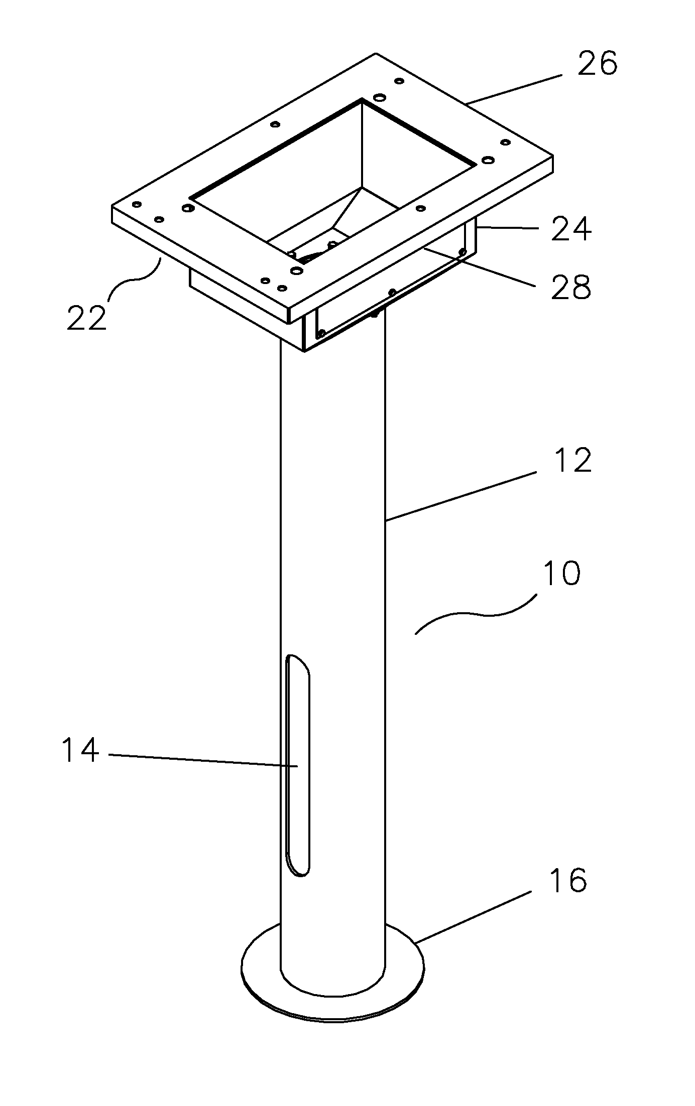
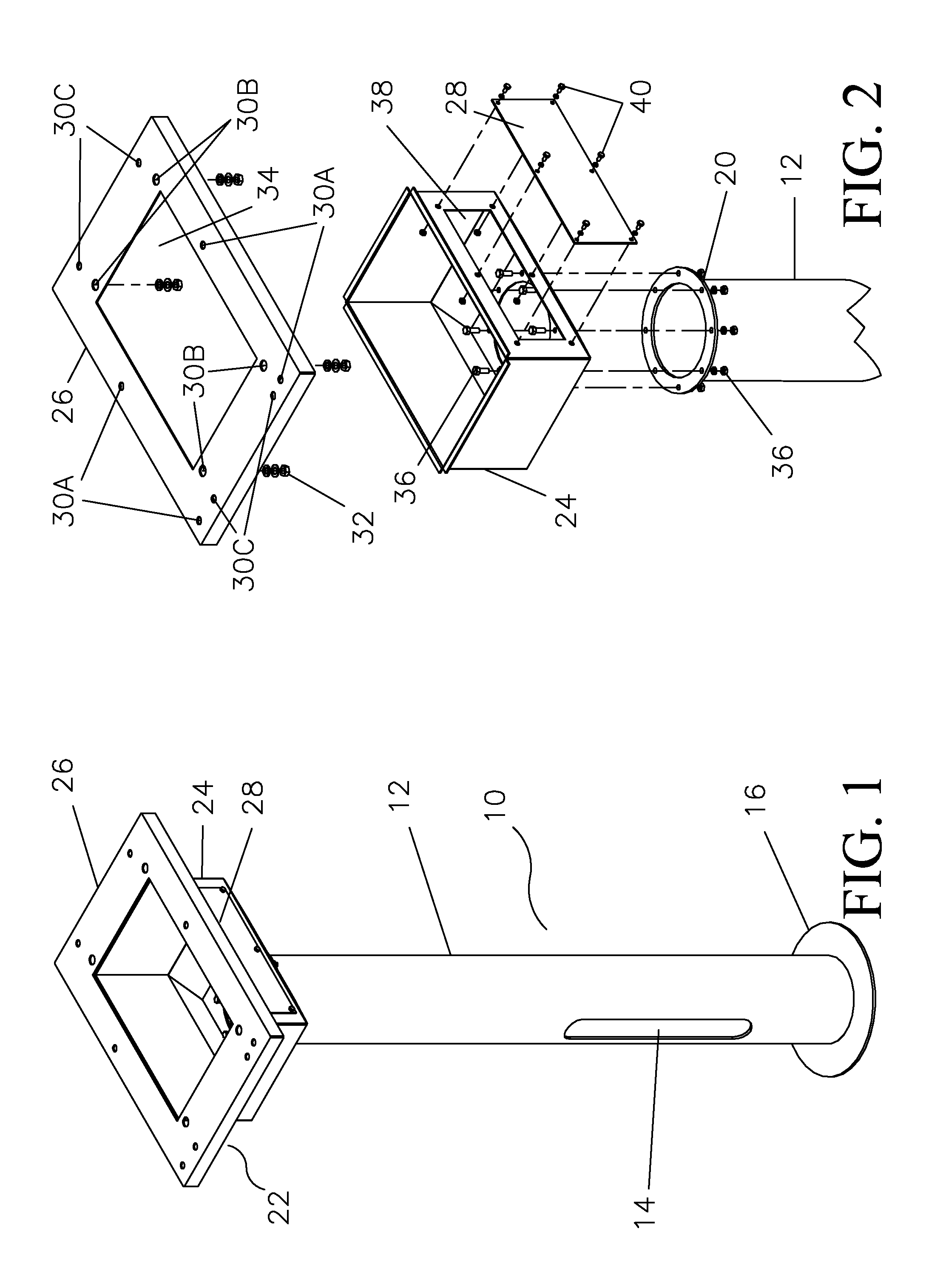
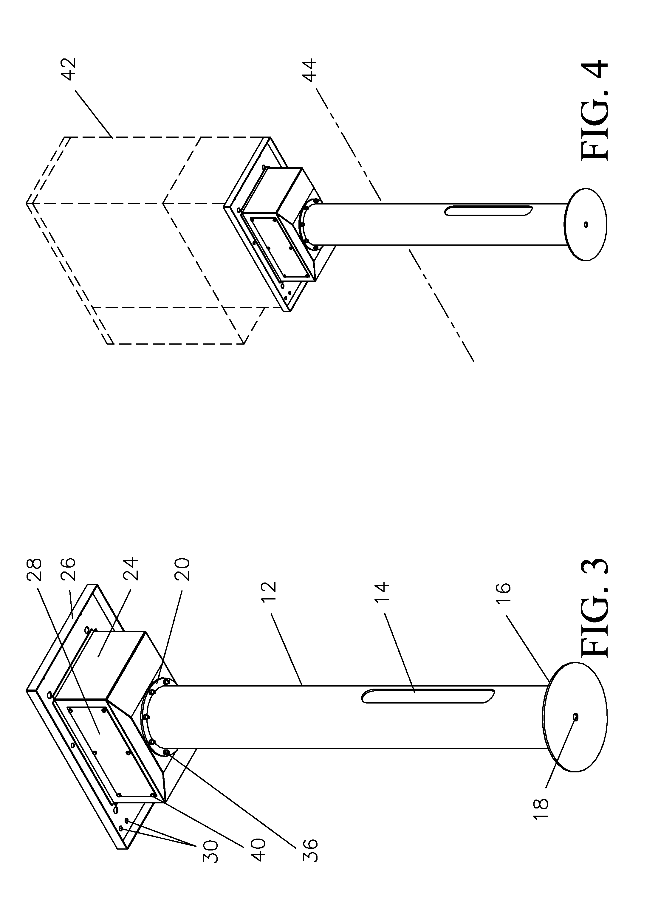
[0016]The one embodiment, the present invention comprises a mounting post assembly configured to accommodate different cabinets. As illustrated in FIG. 1, in one embodiment, the mounting post 10 of the present invention is comprised of two sections; the tubular post 12 and the mounting assembly 22. The post 12 preferably consists of an eight inch diameter aluminum tube that is ¼ inch thick and 64.5 inches in length. There is a ¼ inch thick by 14 inch diameter stabilizer plate 16 welded to the lower end of the post 12.

[0017]As illustrated in FIG. 2, the post 12 has a mounting flange 20 welded to the upper end. Also as illustrated in FIG. 2, the mounting assembly 22 comprises a transition piece 24, which is preferably a 19.3 by 28.7 inch, 11 gauge platform which is bolted to the mounting flange 20 of tube 12 using flange bolts 36. As shown in FIG. 2, transition piece 24 has a circular central opening the bottom surface which conforms to the hollow interior of tube 12 to facilitate rou...


PUM

PropertyMeasurementUnit
thickaaaaaaaaaa
diameteraaaaaaaaaa
thickaaaaaaaaaa

Abstract

A mounting post for supporting a plurality of electronic cabinets, each having different bolt patterns, comprising a hollow post configured to receive a hollow mount at the upper end, a stabilizer plate attached to the lower end of the post, and a hollow mount selected from a plurality of hollow mounts, each having a lower end configured to mate to the post, and having a substantially planar upper surface with openings formed therein corresponding to a unique bolt pattern for an electronics cabinet.

Description

CROSS-REFERENCE TO RELATED APPLICATIONS[0001]This application claims benefit of priority under 35 U.S.C. Section 119(e) to U.S. Provisional Application Ser. No. 61 / 350,398, filed Jun. 1, 2010, entitled “APPARATUS AND METHODS FOR MOUNTING OF CABINETS,” which is hereby incorporated herein by reference.BACKGROUND OF THE INVENTION[0002]1. Field of the Invention[0003]The present invention relates generally to exterior mounting of cabinets that house electronic devices commonly used to provide telecommunication services.[0004]2. Description of the Related Art[0005]Conventional methods for exterior mounting of cabinets that house electronic devices commonly used to provide telecommunication services include utility pole with mount kit, pre-cast pads, and site poured pads.SUMMARY OF THE INVENTION[0006]In accordance with various illustrative embodiments hereinafter described, the present invention is a device that may be used to mount cabinets that house electronic and electrical devices, su...

Claims


Application Information

Patent Timeline
Patent Type & Authority Patents(United States)
IPC IPC(8): A47B96/00A47B81/00A47B97/00A47G29/00A47G23/02A47B91/00A47H1/10A47K1/00
CPCE04C3/32H01Q1/42H01Q1/1242Y10T29/49826
Inventor SKUDIN, MICHAEL E.DAVIS, DENNIS D.WILLIS, DAVID W.
Owner WINDSTREAM INTPROP SERVICES LLC
Why Eureka
Try Eureka