Remotely-aligned arcuate detector array for high energy X-ray imaging

a detector array and high-energy technology, applied in radiation beam directing means, instruments, material analysis using wave/particle radiation, etc., can solve the problems of detectors not being in the optimal position, processing is substantially more arduous, laborious and laborious,

Active Publication Date: 2013-05-14
AMERICAN SCI & ENG INC
View PDF16 Cites 38 Cited by
  • Summary
  • Abstract
  • Description
  • Claims
  • Application Information

AI Technical Summary

Problems solved by technology

Moreover, the process is made substantially more arduous if the geometry of the system is anything other than rectilinear.
The time consuming nature of the process results in a labor intensive effort that can be quite costly and ultimately the detectors may not end up in an optimal position.
Since the use of optical alignment tools requires line of sight from the various components in order to function, the alignment process can require the removal of covers to gain access to the detectors and adjustors and may expose the detectors and other sensitive components within the equipment to potentially damaging environmental factors.
The incorporation of these technologies makes the detector modules more sensitive to misalignment than traditional detector modules, and, if the geometry of the system is non-rectilinear, the alignment is all the more difficult.

Method used


Image

  • Remotely-aligned arcuate detector array for high energy X-ray imaging
  • Remotely-aligned arcuate detector array for high energy X-ray imaging
  • Remotely-aligned arcuate detector array for high energy X-ray imaging

Examples


Embodiment Construction

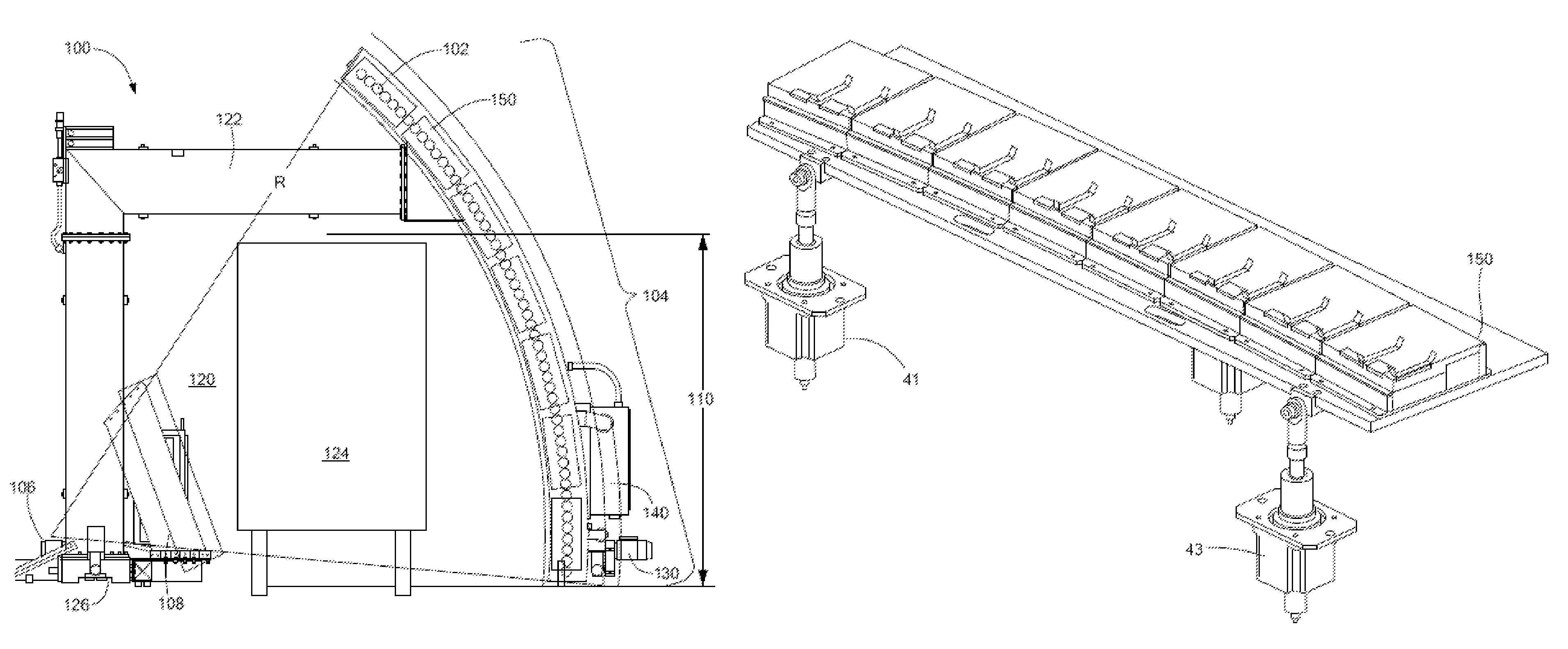
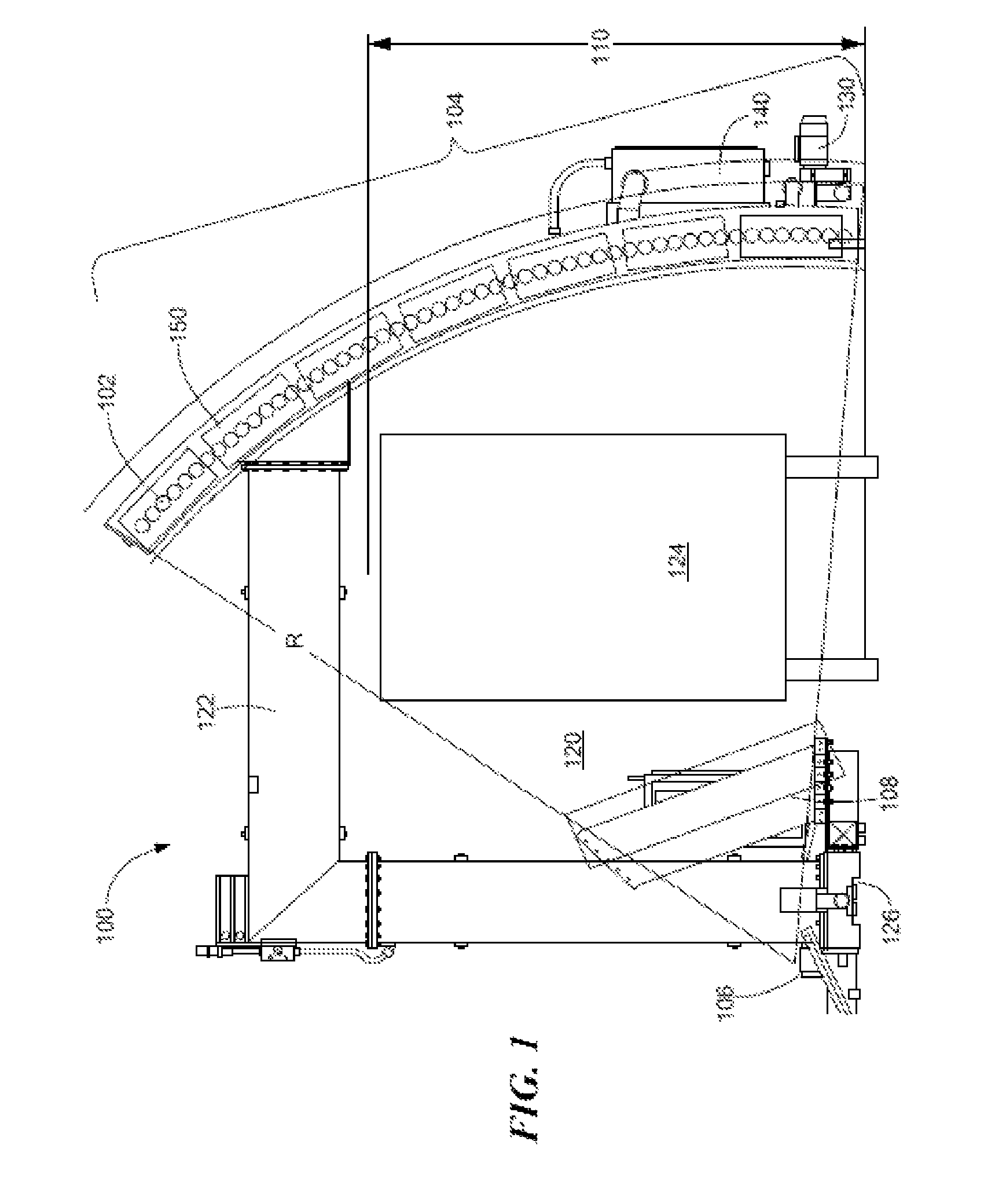
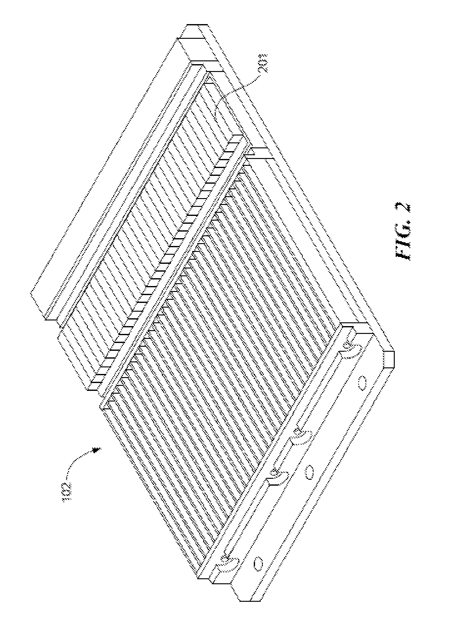
[0012]In accordance with various embodiments of the present invention, methods and apparatus are provided for inspecting large objects by x-ray transmission by means of a curvilinearly disposed array of detectors coaligned to a single source of penetrating radiation by active alignment of detector plates during the course of irradiation by the source itself.

[0013]In accordance with one embodiment of the invention, a scanning system is provided for inspecting contents of an inspected container. The scanning system has a source of penetrating radiation of peak energy exceeding 1 MeV and a collimator having an exit slot for forming the penetrating radiation into a fan beam characterized by a transverse dimension as measured at the exit slot. A plurality of detector plates are arcuately disposed at a distance exceeding 5 meters from the source of penetrating radiation, where each detector plate has a plurality of detector modules. Each detector module, in turn, has a plurality of detect...


PUM

PropertyMeasurementUnit
peak energyaaaaaaaaaa
distanceaaaaaaaaaa
thicknessaaaaaaaaaa

Abstract

A scanning system and methods for inspecting contents of a container. High-energy penetrating radiation collimated into a fan beam illuminates an inspected container from one side, while a plurality of detector plates are disposed on the opposite side of the container. Each detector plate has a plurality of detector modules, each of which, in turn, is disposed on a remotely activated alignment and has multiple detector elements. A controller governs the orientation of each of the plurality of detector plates based at least on the detector signal generated by its detector elements such that each detector element of each detector module of each detector plate may be aligned to within a specified fraction of the transverse dimension of the fan beam as measured at the exit slot.

Description

[0001]The present application claims the priority of U.S. Provisional Patent Application Ser. No. 61 / 393,481, filed Oct. 15, 2010, and of U.S. Provisional Patent Application Ser. No. 61 / 414,482, filed Nov. 17, 2010, both of which applications are incorporated herein by reference.TECHNICAL FIELD[0002]The present invention relates to systems and methods for detecting high-energy penetrating radiation, and more particularly to the application of such systems and methods to the inspection of cargo and cargo-carrying vehicles with high-energy x-rays.BACKGROUND ART[0003]X-ray security inspection systems for cargo and shipping containers typically use transmission radiographic techniques. A high inspection throughput of cargo and cargo-carrying vehicles is at a premium. Consequently, it is desirable that an entire plane through the cargo be probed simultaneously, and one inspection modality employs a fan-shaped beam to produce images of a target object while the fan beam and detectors are ...

Claims


Application Information

Patent Timeline
Patent Type & Authority Patents(United States)
IPC IPC(8): G01N23/04H05G1/64
CPCG01N23/04G01V5/0016
Inventor MASTRONARDI, RICHARDDENKER, JEFFREY M.ROTHSCHILD, PETERDINCA, DAN-CRISTIANPAILES, AARON D.BLAKE, DAVID R.MARTIGNETTI, DOMENIC
Owner AMERICAN SCI & ENG INC
Why Eureka
Try Eureka