Radiation-emitting device

Active Publication Date: 2013-05-14
OSRAM OLED
View PDF12 Cites 5 Cited by
  • Summary
  • Abstract
  • Description
  • Claims
  • Application Information

AI Technical Summary

Benefits of technology

[0005]It is an object of the invention to provide a radiation-emitting device which has an emitter layer w

Problems solved by technology

Long lives, however, cannot be real

Method used


Image

  • Radiation-emitting device
  • Radiation-emitting device
  • Radiation-emitting device

Examples


Example

DETAILED DESCRIPTION OF THE DRAWINGS

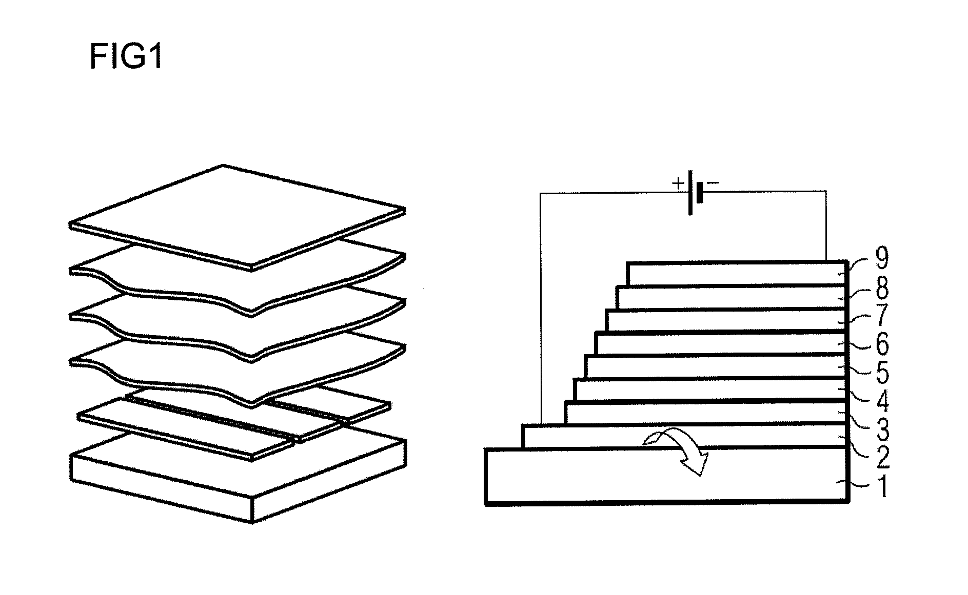
[0058]FIG. 1 shows the schematized layer construction of an organic, radiation-emitting component. From bottom to top, the following layer construction is realized: at the very bottom is the substrate 1, which may, for example, be transparent and may also be made of glass. Atop it is a lower electrode layer 2, which may, for example, be a transparent conductive oxide such as indium tin oxide (ITO). This lower electron layer may function as anode or as cathode. Disposed above this electrode layer 2 is a hole injection layer 3, above which in turn is disposed a hole transport layer 4. Disposed above the hole transport layer 4 is the organically active layer, the emission layer 5. Where the radiation-emitting device comprises more than one emission layer 5, the first emission layer is followed by the further emission layers, optionally separated by exciton blocking layers.

[0059]Lying on the emission layer or on the two or more emission layers is the ...


PUM

PropertyMeasurementUnit
Fractionaaaaaaaaaa
Fractionaaaaaaaaaa
Percent by massaaaaaaaaaa

Abstract

A radiation-emitting device having comprising: a substrate (1); a first electrode (2) and a second electrode; (9), at least one emitter layer (5) arranged between the first and second electrodes and emitting light in the violet or blue spectral range, wherein the emitter layer comprises a matrix material and, relative to the matrix material, 0.1%-5% by weight of a fluorescent, radiation-emitting emitter and 1-30% by weight of a phosphorescent exciton trap; and wherein the emission maximum of the fluorescent emitter and that of the phosphorescent exciton trap being situated in the blue, violet or ultraviolet spectral range.

Description

RELATED APPLICATIONS[0001]This is a U.S. national stage of application No. PCT / EP2010 / 055368, filed on Apr. 22, 2010.[0002]This application claims the priority of German application no. 10 2009 018 647.6 filed Apr. 23, 2009, the entire content of which is hereby incorporated by reference.FIELD OF THE INVENTION[0003]The present invention relates to a radiation-emitting device having an emitter layer which comprises a matrix material, a radiation-emitting fluorescent emitter, and an exciton trap.BACKGROUND OF THE INVENTION[0004]Highly efficient emitters with a very long life are one of the prerequisites for the development of high-efficiency organic light-emitting diodes (OLEDs) and for display and lighting applications. Critical to a high efficiency is the quantum efficiency of the individual emitter molecule and the quantum efficiency of the emitter system (made up of matrix and radiation-emitting emitter) overall. Long lives, however, cannot be realized equally for all emitted colo...

Claims


Application Information

Patent Timeline
IPC IPC(8): H01L51/00
CPCH01L51/5012H01L51/5016H01L51/5036H10K50/125H10K50/11H10K2101/10H10K50/16H10K50/15
Inventor HUNZE, ARVIDCHIU, CHIEN-SHUKRAUSE, RALF
Owner OSRAM OLED
Why Eureka
Try Eureka