Optical arrangement, method of use, and method for determining a diffraction grating

a technology applied in the field of optical arrangement and diffraction grating, can solve the problems of steep drop in the efficiency of response of the diffraction grating in the selected configuration, the paper's validity loss of te polarization theorem, and the failure to display a perfect blaze effect of the diffraction grating, etc., to achieve the effect of improving the blaze

Active Publication Date: 2013-05-14
CARL ZEISS SMT GMBH
View PDF4 Cites 2 Cited by
  • Summary
  • Abstract
  • Description
  • Claims
  • Application Information

AI Technical Summary

Benefits of technology

[0025]The disclosure provides an optical arrangement that provides an improved blaze effect.
[0027]The optical arrangement according to the disclosure departs from the known concept of tuning the Littrow angle θL to the grating such that the Littrow angle θL is virtually equal to the angle β of the blaze flanks to the base surface of the diffraction grating. By contrast, the disclosure proceeds from another concept, specifically of selecting for a given Littrow angle the angle β of the blaze flanks to the base surface as a function of the Littrow angle, and indeed such that the diffraction efficiency is at least approximately maximal in one of the largest propagating diffraction orders m, which still fulfils the condition (2((m+1) / m)−1)sin θL≧1, and for at least one polarization direction (TE or TM). To be precise, it has surprisingly been found that the diffraction efficiency in the blaze order can be increased when the angle β deviates from the Littrow angle θL by more than the maximum value of 1° permitted in the prior art. As stated in yet more detail in the following description, it is thereby possible to achieve a perfect blaze effect of 100% in the case of a diffraction grating made from an ideally conducting material, specifically for both polarization directions, and for materials of finite conductivity the diffraction efficiency in the blaze order is reduced only by the absorption of the light by the material. The present disclosure can be used to disprove the property, assumed as known in the abovenamed technical book and the abovenamed paper, that a perfect blaze effect in both polarization directions is impossible. The disclosure thus enables the use of substantially better diffraction gratings than is the case in the prior art.
[0029]This measure now has the particular advantage that substantively lesser requirements are to be placed on the manufacturing tolerance of the diffraction grating. To be precise, the angle β of the blaze flanks can be selected from a specific angular range of a few degrees, or can vary in this angular range, without the diffraction efficiency in the blaze order dropping appreciably from the maximum. This angular tolerance of the blaze flanks is enabled firstly by the disclosure, specifically by the selection of the angle β of the blaze flanks to the base surface as a function of the Littrow angle θL.
[0034]This measure increases the total diffraction efficiency in the blaze order still further, because the selection of the angle β of the blaze flanks to the base surface is optimized as a function of the Littrow angle for both polarization directions. Admittedly, this narrows down the angular range from which the angle β of the blaze flanks to the base surface can be selected, and it thereby also depresses the angular tolerance of the angle β, but the total diffraction efficiency in the blaze order considered is further increased.
[0038]Using such an optical arrangement and such a diffraction grating, a diffraction efficiency at least near the perfect blaze effect which simultaneously includes a high angular tolerance of the angle (β) is attained.
[0044]In the event of such a use, the useful properties of the optical arrangement according to the disclosure, specifically maximal diffraction efficiency in the blaze order with less-diffracted light in other diffraction orders, can be used with particular advantage.

Problems solved by technology

Although the production of diffraction gratings continued to be improved yet further, some diffraction gratings do not, however, display a perfect blaze effect, that is to say in addition to the diffracted light of the desired blaze order, whose intensity has a maximum, light is also always to be found in further diffraction orders which therefore subtract intensity from the desired blaze order.
However, the theorem from the paper loses its validity for TE polarization, in the case of which other conditions placed on the electromagnetic optical field are present than in the case of TM polarization.
An overshooting of this angular tolerance can lead to a steep drop in the efficiency of response of the diffraction grating in the selected configuration.

Method used


Image

  • Optical arrangement, method of use, and method for determining a diffraction grating
  • Optical arrangement, method of use, and method for determining a diffraction grating
  • Optical arrangement, method of use, and method for determining a diffraction grating

Examples


Embodiment Construction

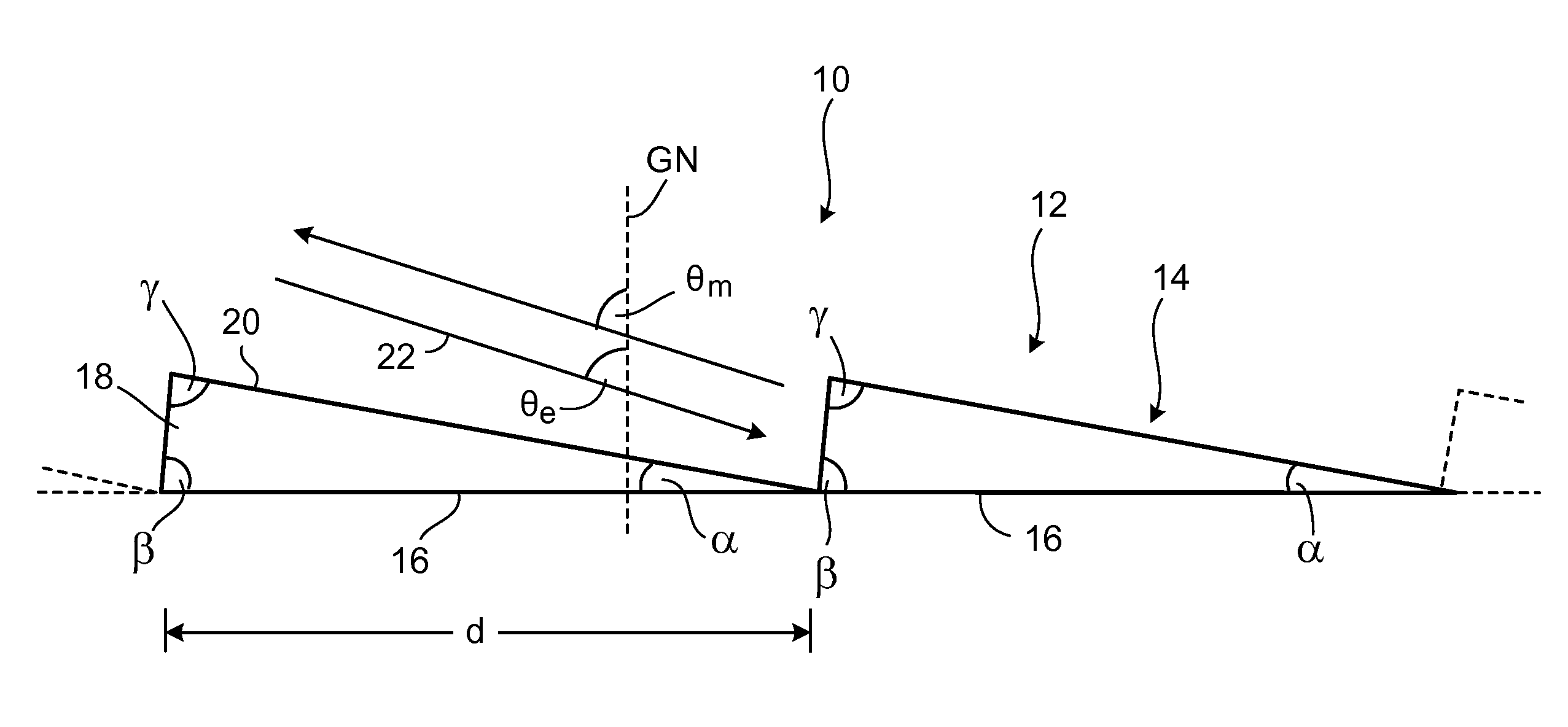
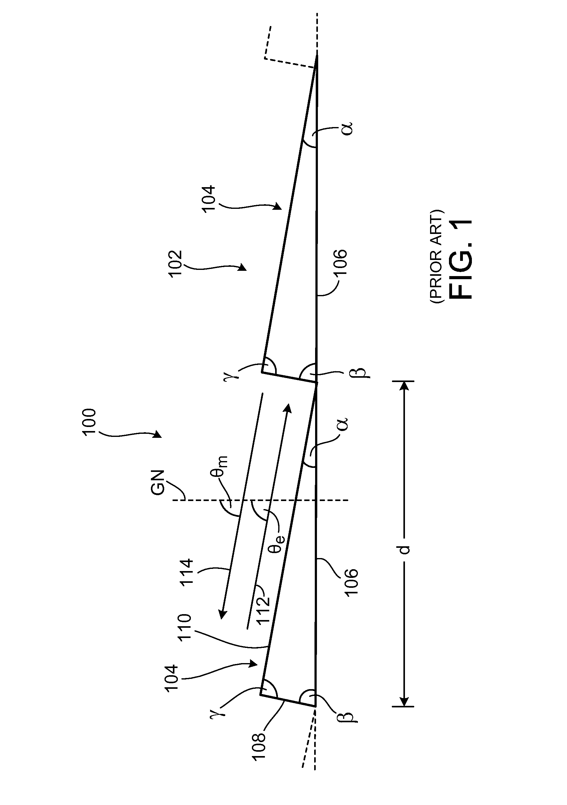
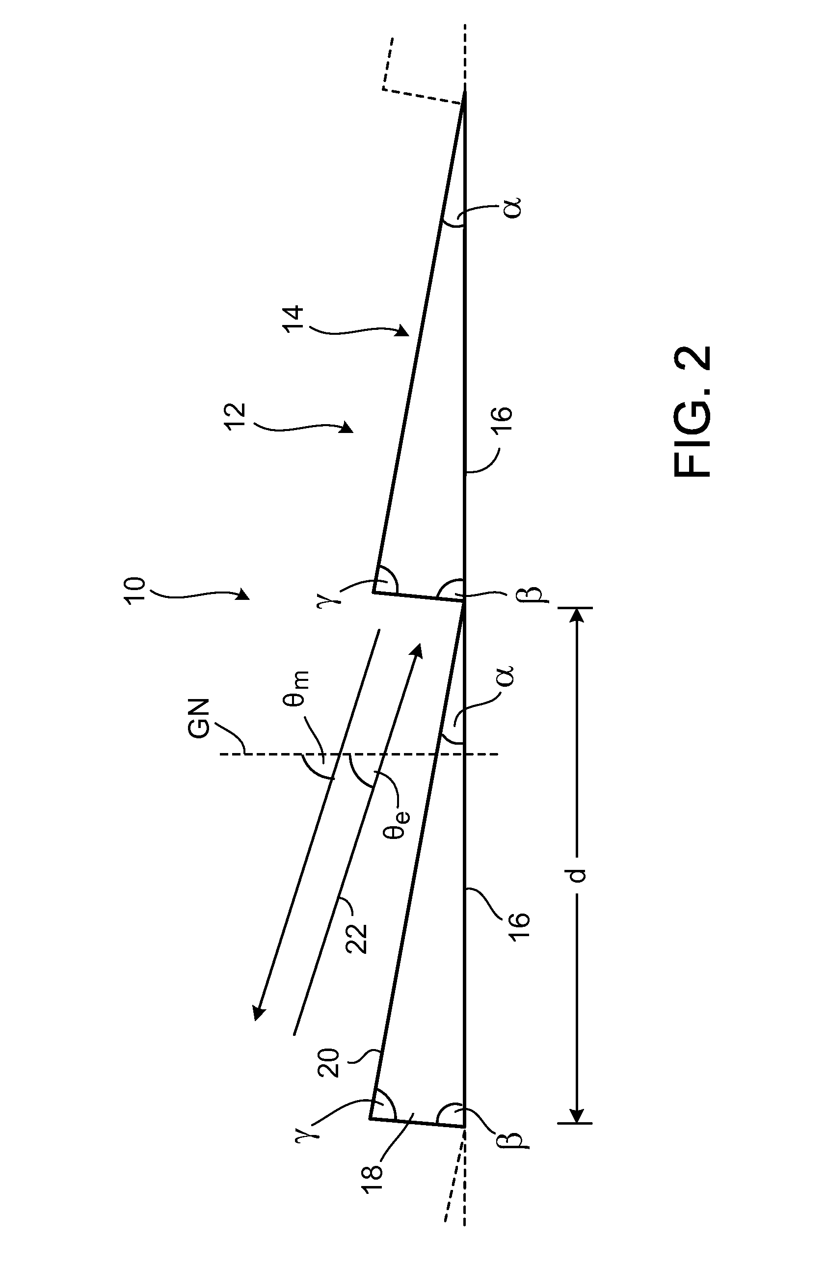
[0067]Before the present disclosure is considered in detail, the prior art is firstly described briefly once more with reference to FIG. 1, in order to emphasize the differences and advantages of the present disclosure by comparison with the prior art with the aid of this description.

[0068]The first step to this end is to consider an example which is described in the document U.S. Pat. No. 6,067,197. In a first case, the incident light beam 112 in accordance with FIG. 1 contains light of a wavelength λ of 248.4 nm, which is emitted by a KrF laser. In a second case, the light beam 112 with a wavelength λ of 193.3 nm is emitted by an ArF laser.

[0069]It was found in U.S. Pat. No. 6,067,197 that the 84th diffraction order (m=84) in the case of the KrF laser, and the 108th diffraction order (m=108) in the case of the ArF laser, simultaneously constitute a blaze order when the grating width d of the diffraction grating 102 is 10.623 μm and the angle β of the blaze flanks 108 to the base s...


PUM


Abstract

An optical arrangement includes a light source which emits coherent light of a wavelength λ, and a diffraction grating which has a multiplicity of diffraction structures which follow one another periodically at the spacing of a grating period d and are arranged along a base surface, the individual diffraction structures respectively having a blaze flank and an antiblaze flank, the blaze flanks being arranged at an angle β and the antiblaze flanks being arranged at an angle α to the base surface, and respectively neighbouring blaze and antiblaze flanks enclosing an apex angle γ, and an incident light beam being arranged at a Littrow angle θL relative to a grating normal of the diffraction grating. The angle β of the blaze flanks to the base surface is selected as a function of the Littrow angle θL such that the diffraction efficiency is at least approximately maximal in one of the largest diffraction orders m, which still fulfils the condition (2((m+1) / m)−1)sin θL≧1, and for at least one polarization direction.

Description

CROSS-REFERENCE TO RELATED APPLICATION[0001]The application claims priority under 35 U.S.C. §119 to German Patent Application No. 10 2009 031 688.4 filed on Jun. 26, 2009, the entire contents of which are hereby incorporated by reference.FIELD[0002]The disclosure generally relates to optical arrangements having diffraction gratings, and to diffraction gratings, such as an optical arrangement, including a light source which emits coherent light of a wavelength (λ), and a diffraction grating which has a multiplicity of diffraction structures which follow one another periodically at the spacing of a grating period (d) and are arranged along a base surface, the individual diffraction structures respectively having a blaze flank and an antiblaze flank, the blaze flanks being arranged at an angle (β) and the antiblaze flanks being arranged at an angle (α) to the base surface, and respectively neighbouring blaze and antiblaze flanks enclosing an apex angle (γ), and an incident light beam b...

Claims


Application Information

Patent Timeline
Patent Type & Authority Patents(United States)
IPC IPC(8): G02B5/18G02B27/44
CPCG02B5/1861G02B5/1866
Inventor KLEEMANN, BERND
Owner CARL ZEISS SMT GMBH
Why Eureka
Try Eureka