

Whole beam image splitting system
a technology of image splitting and whole beam, which is applied in the field of multi-beam image splitting system, can solve the problems of not describing the method of optically producing multiple images on multiple sensor arrays simultaneously, and the method of splitting an image-forming beam into sub-images
- Summary
- Abstract
- Description
- Claims
- Application Information
AI Technical Summary
Benefits of technology
Problems solved by technology
Method used
Image

Examples
embodiment 100
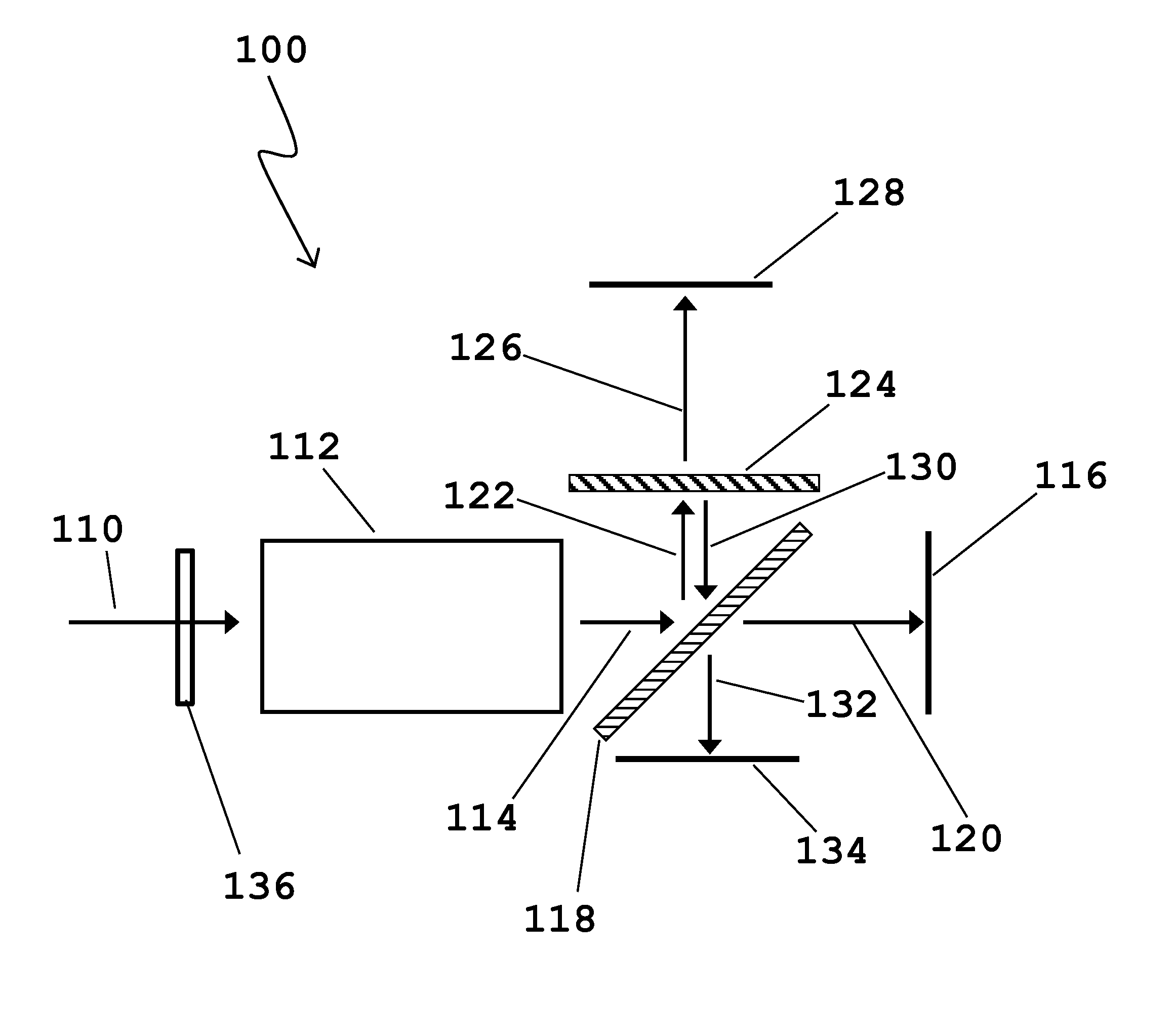
[0069]FIG. 1A is a schematic diagram of embodiment 100 of the present invention which utilizes a pair of beamsplitters to split the light from a single imaging system so as to produce three spatially-identical images on three separate detector planes. Referring to FIG. 1A, optical radiation 110 preferably from an object (not shown) is incident on imaging lens system 112. Any imaging or image forming lens system may be used in this embodiment of the invention. For example, any of the camera lenses manufactured by Nikon, Olympus, Panavision, or Thales Angenieux may be used as imaging lens system 112. If the back focal length of a desired camera lens is too short for use with the present invention, imaging lens system 112 may optionally include a re-imaging lens. For another example, imaging lens system 112 may comprise a cinematography camera lens manufactured by Zeiss, followed by an optional field stop (simply a rectangular aperture designed to block stray light rays), followed by a...
embodiment 1300
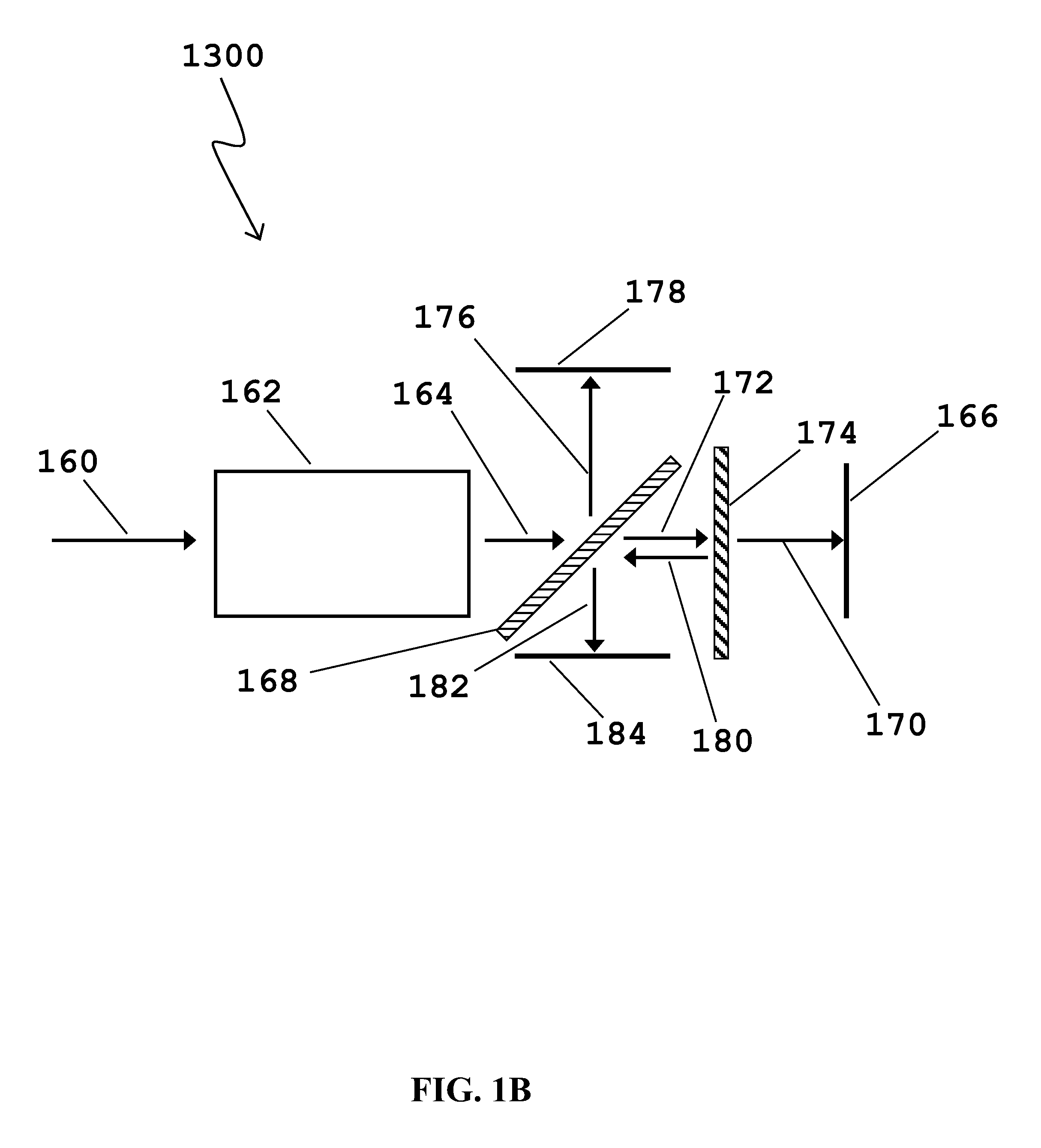
[0079]FIG. 1B is a schematic diagram of embodiment 1300 of the present invention. Referring to FIG. 1B, optical radiation 160 preferably from an object (not shown) is incident on imaging lens system 162. Image-forming beam 164 exits the imaging lens system 162 as a converging image beam and is incident on beamsplitter 168, preferably oriented at a 45-degree angle to the path of image-forming beam 164, although any angle in the range between 0 and 180 degrees may be used. Beamsplitter 168 is preferably thin; for example it may be 0.5 mm thick and comprise glass with flat and parallel front and back surfaces; or alternatively it may comprise a so-called “pellicle” beamsplitter, such as Part Number NT39-482 from Edmund Optics.
[0080]As a result of this beamsplitter arrangement, first reflected beam portion 176 is directed toward image sensor 178, where it forms an image, and first transmitted beam portion 172 is incident on beamsplitter 174, which is preferably oriented perpendicular to...
embodiment 200
[0084]FIG. 2 is a schematic diagram of embodiment 200 of the present invention. Referring to FIG. 2, optical radiation 210 preferably from an object (not shown) is incident on imaging lens system 212. Image-forming beam 214 exits imaging lens system 212 as a converging image beam and is incident on beamsplitter 218, which is preferably oriented at a 45-degree angle to the path of image-forming beam 214, although any angle in the range between 0 and 180 degrees may be used. As a result, first transmitted beam portion 220 continues toward image sensor 216, and first reflected beam portion 222 is reflected toward beamsplitter 224, which is preferably oriented perpendicular to first reflected beam portion 222. As a result, second transmitted beam portion 226 passes through beamsplitter 224 and forms an image on image sensor 228. Second transmitted beam portion 226 typically does not need to pass through a corrective lens system since neither it nor light beams 210, 214, or 222 ever pass...
PUM
 Abstract
Description
Claims
Application Information