
Degassing device

a degassing device and liquid technology, applied in liquid degassing, water/sewage treatment by degassing, separation processes, etc., can solve the problems of air embolism, permanent brain damage, and serious damage to body functions, so as to reduce the effect of effectiveness, prolong the life, and maximize the advantages

Active Publication Date: 2013-05-21
GAMBRO LUNDIA AB
View PDF21 Cites 20 Cited by
  • Summary
  • Abstract
  • Description
  • Claims
  • Application Information

AI Technical Summary

Benefits of technology

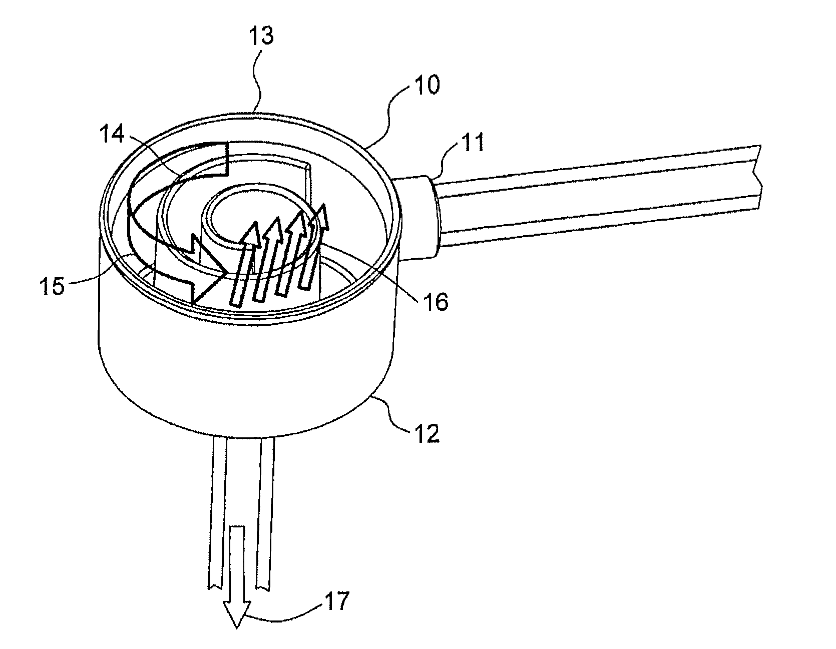
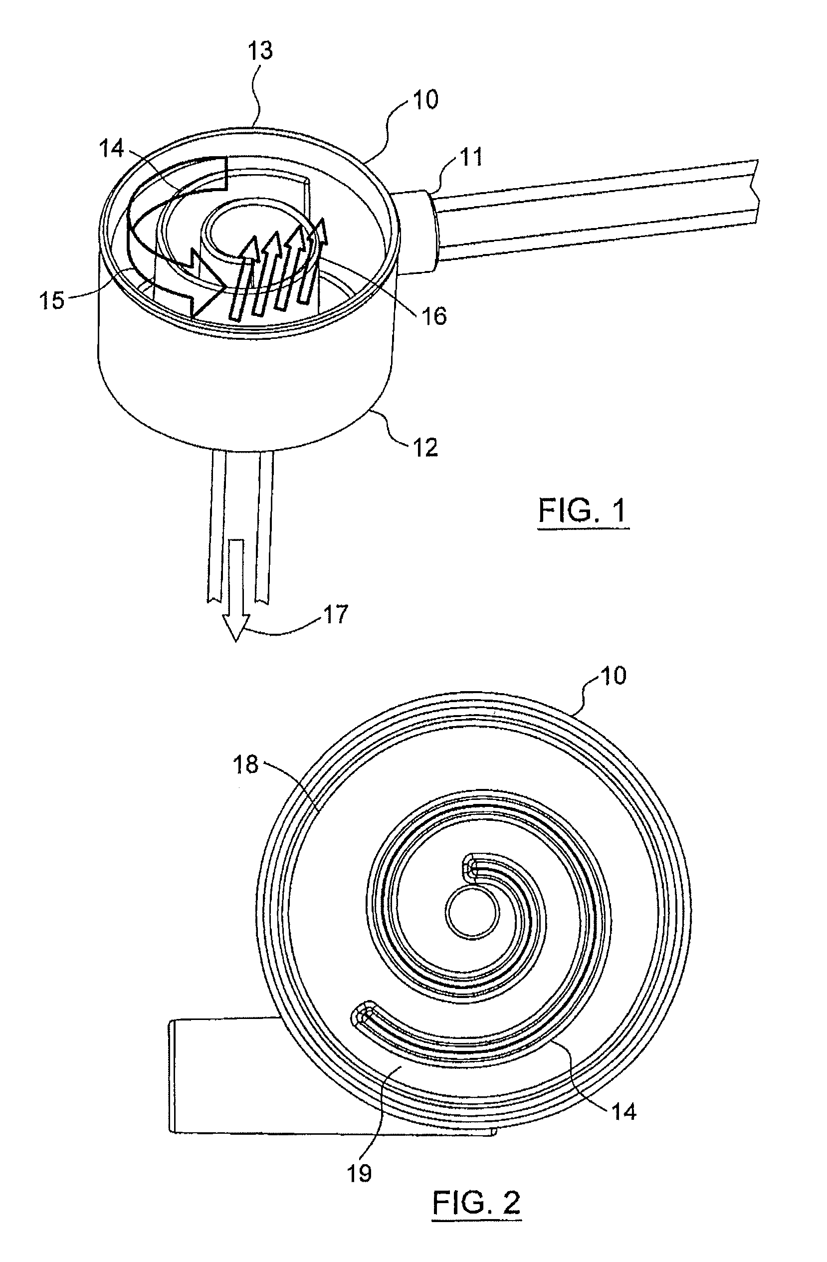
[0021]The degassing device significantly reduces the total volume within the chamber in comparison to the degassing devices known in the art, where air cushions are formed in an upper area. In the present device, no air cushion will form as the bubbles, which are separated from the fluid, are immediately removed from the system through the hydrophobic membrane. In devices in which an air cushion is formed, the inflow must be placed as far away from this upper area in order to stabilize the fluid layer and to avoid renewed introduction of air. This necessitates chambers with a substantial overall height and, as a consequence, the degassing devices will accommodate a relatively large amount of blood. The degassing device according to the present disclosure does not need such height of the chamber, which can in contrast be minimized, thus significantly reducing the blood volume in the degassing device and making the degassing device economic from a material consumption point of view. Such reduced blood volume also minimizes the contact to extracorporeal surfaces, thus reducing the risk of activation of blood components.
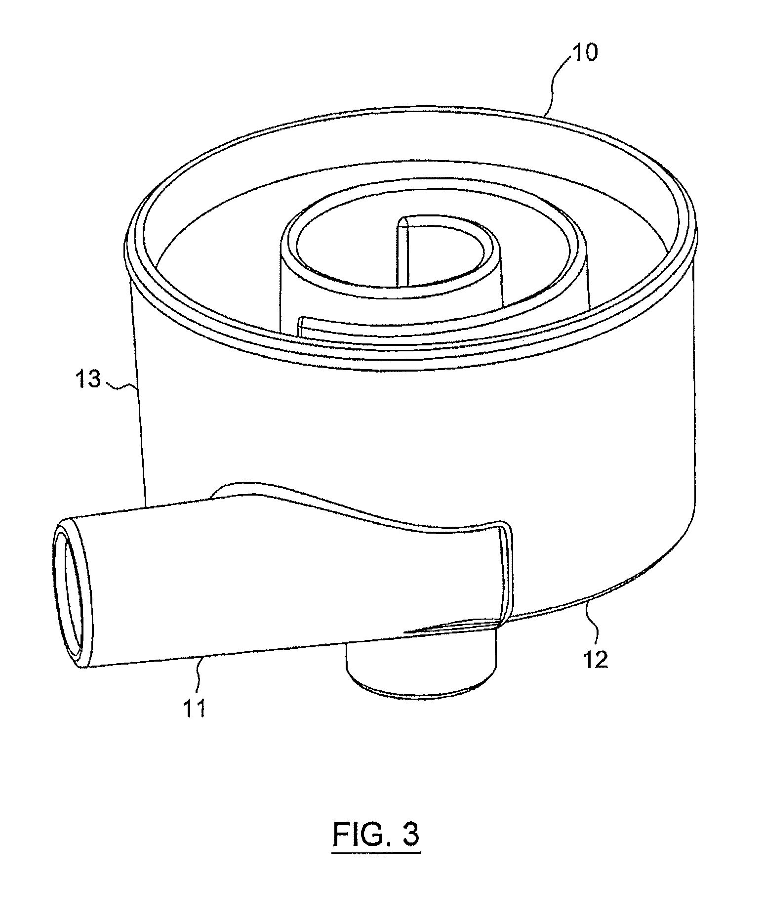
[0042]The cover and the body of the chamber may be joined in any suitable manner. For example, the lower end of the cover side wall may include an annular channel formed in a flange which is configured in such a manner to receive the open upper end of the body of the chamber. The cover and the body may then be joined at the channel, for example by bonding or welding, so that the entire unit is disposed of when the element needs replacement. The cover may also be removably positioned on the chamber for easy replacement when needed.

Problems solved by technology

Even if these bubbles of gas are only of very small size, they can cause serious damage to body functions by causing air embolism.
Air embolism occurs when bubbles of air become trapped in the circulating blood.
Eventually, it will block a small artery, which is serious because the blockage will cut off the blood supply to some area of the body.
If, for example, the embolism prevents blood supply to the brain, tissues will be starved of oxygen, causing them to die, thus likely resulting in permanent brain damage.
This necessitates chambers with a substantial overall height and, as a consequence, the degassing devices will accommodate a relatively large amount of blood.
In devices wherein the membrane is not permanently contacting the liquid, especially blood, the membrane tends to loose its permeability over time.
A larger or smaller distance generally results in a decrease of the degassing efficiency.
Flows below 100 ml / min will result in a decrease in efficiency in removing air from the fluid, even though the degassing device can also be used at lower flow rates.

Method used


Image

  • Degassing device
  • Degassing device
  • Degassing device

Examples


examples

[0081]The spiral degassing device according to the present disclosure shows an exceedingly well performance with regard to degassing of a liquid, especially of blood, both in in vitro and in in vivo tests.

1. Removal of Air In Vitro

[0082]In an in vitro test with bovine blood (hematocrit between 32 and 40, total protein content: 60-80 g / l) the efficacy of the degassing device according to the present disclosure was tested by injecting air into the corresponding system (FIG. 6). The setup essentially consisted of a circular flow of blood, comprising one liter of blood (bovine blood) at a temperature of 37° C., a pressure manometer, a degassing device according to the present disclosure, a dialyzer (Polyflux® 170 H, Gambro), a drip chamber and the corresponding tubing. Further, the system comprised a first air injection port S1 and a second air injection port S2, with the first air injection port S1 being located before and the second air injection port S2 being located after the pressu...


PUM

PropertyMeasurementUnit
distanceaaaaaaaaaa
distanceaaaaaaaaaa
inner diameteraaaaaaaaaa

Abstract

A device for degassing gas bubbles out of a liquid comprises a housing having a liquid inlet, a liquid outlet and a gas bubble outlet. The housing includes a spiral wall defining a spiral flow path for the liquid and a hydrophobic membrane above the spiral wall and between the spiral wall and the gas bubble outlet. The spiral wall forces inward liquid entering the housing through the inlet into a spiral flow along the spiral flow path, and causes an upward flow of the gas bubbles toward the hydrophobic membrane. A method for degassing gas bubbles out of a liquid, e.g., blood, e.g., during hemodialysis, hemofiltration and hemodiafiltration, and use of such a degassing device in an extracorporeal circuit for degassing gas bubbles out of liquid, e.g., blood, e.g., during hemodialysis, hemofiltration and hemodiafiltration, are disclosed.

Description

CROSS-REFERENCE TO RELATED APPLICATIONS[0001]This application is the U.S. national phase of PCT / EP2009 / 003068 filed Apr. 28, 2009. PCT / EP2009 / 003068 claims priority to European patent application EP 08008247.2 filed Apr. 30, 2008. The disclosure of both of EP 08008247.2 and PCT / EP2009 / 003068 are hereby incorporated herein by reference.TECHNICAL FIELD[0002]The present disclosure relates to a degassing device, and particularly to a degassing device for liquids, especially for blood, which is used in extracorporeal circuits for the treatment of blood.DESCRIPTION OF THE RELATED ART[0003]Degassing devices are used in various treatments of blood, such as blood autotransfusion and cell separation during an operation, such as, for example, cardiopulmonary bypass procedures, but also especially in hemodialysis, hemofiltration, haemodiafiltration or plasmapheresis applications. In all these treatments, blood is withdrawn from a patient, flown through a filter, such as a dialyzer, and returned...

Claims


Application Information

Patent Timeline
Patent Type & Authority Patents(United States)
IPC IPC(8): A61M1/00A61M1/14A61M1/36A61M37/00A61M1/38B04C1/00B01D19/00
CPCA61M1/3627B01D19/0057A61M2206/16A61M2205/7536A61M1/16
Inventor BECK, CHRISTOF
Owner GAMBRO LUNDIA AB
Learn More