Method of cutting substrate

a substrate and cutting technology, applied in the direction of glass tempering apparatus, electric/magnetic/electromagnetic heating, instruments, etc., can solve the problems of existing methods, difficult simultaneous cutting of substrates, and difficult cutting of substrates, and achieve effective and stab cutting of panels

Active Publication Date: 2013-05-21
SAMSUNG DISPLAY CO LTD
View PDF18 Cites 55 Cited by
  • Summary
  • Abstract
  • Description
  • Claims
  • Application Information

AI Technical Summary

Benefits of technology

[0009]The present teachings provide a substrate cutting method to effectively and stably cut a panel including a plurality of substrates.

Problems solved by technology

However, existing methods, such as methods using a blade or a laser beam, are problematic, in that the separation between the glass substrates makes simultaneously cutting the substrates difficult.
In other words, the existing methods are problematic, in that while simultaneously cutting a pair of glass substrates, edge portions of one or both of the glass substrates are likely to be damaged during cutting.

Method used


Image

  • Method of cutting substrate
  • Method of cutting substrate
  • Method of cutting substrate

Examples


Embodiment Construction

[0032]Reference will now be made in detail to the exemplary embodiments of the present teachings, examples of which are illustrated in the accompanying drawings, wherein like reference numerals refer to the like elements throughout. The exemplary embodiments are described below, in order to explain aspects of the present teachings, by referring to the figures.

[0033]In the drawings, the thickness of layers, films, panels, regions, etc., are exaggerated for clarity. The thicknesses of the layers, films, panels, regions, etc., are enlarged in the drawings for better understanding and ease of description. It will be understood that when an element such as a layer, film, region, or substrate is referred to as being disposed “on” another element, it can be disposed directly on the other element, or intervening elements may also be present.

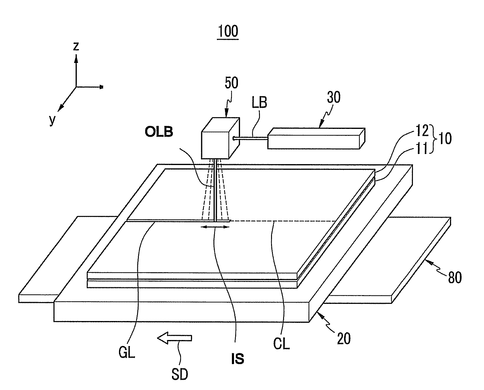
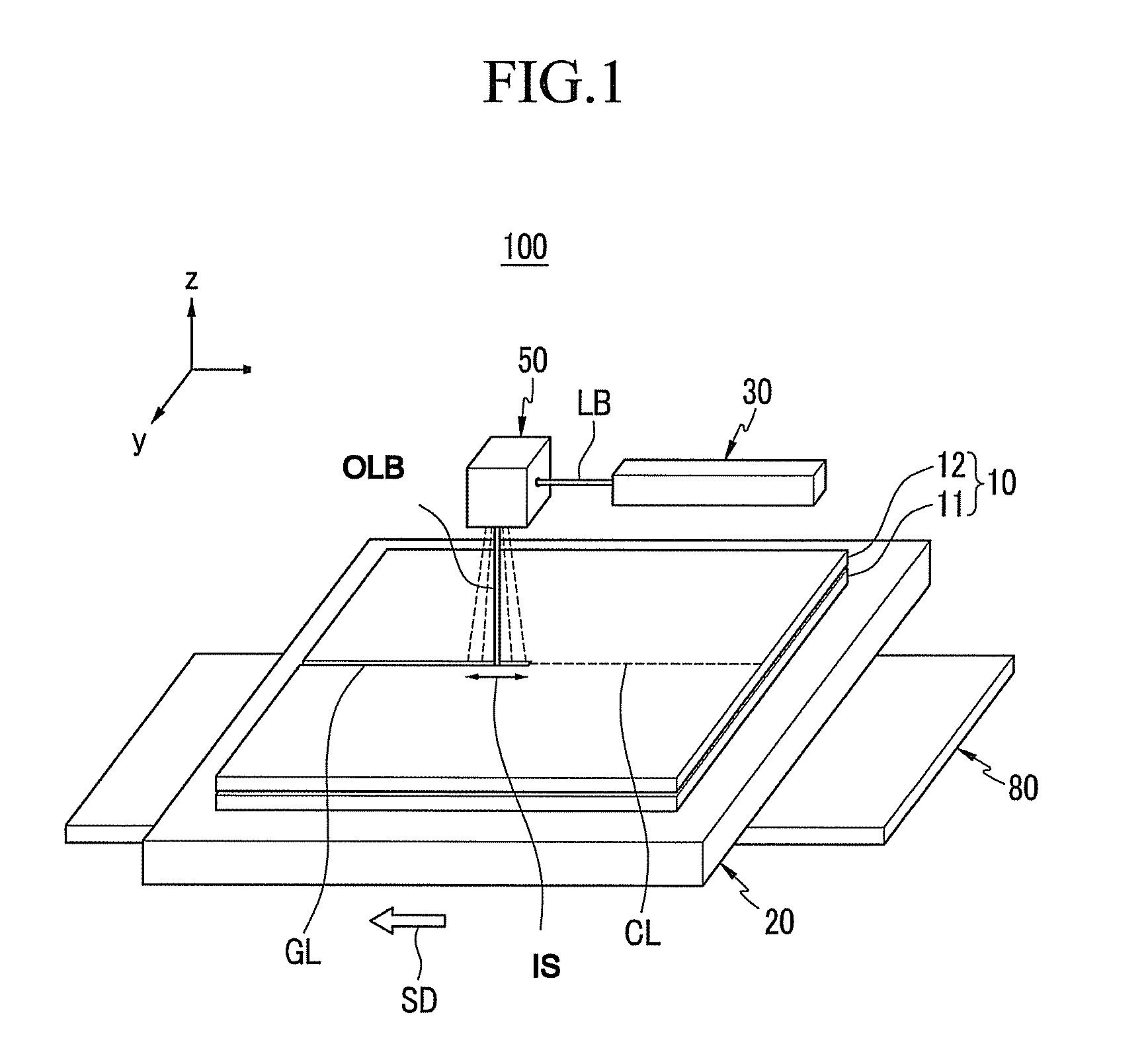
[0034]Hereinafter, a substrate cutting apparatus 100, according to an exemplary embodiment of the present teachings, is described with reference to FIG....


PUM

PropertyMeasurementUnit
wavelengthaaaaaaaaaa
timeaaaaaaaaaa
pulse frequencyaaaaaaaaaa

Abstract

A substrate cutting method includes the steps of aligning a panel including two or more substrates, along a cutting line, forming groove lines in the respective substrates of the panel along the cutting line, by oscillating respective ultraviolet UV laser beams along the cutting line, and cutting the panel along the groove lines, by applying force to the panel.

Description

CROSS-REFERENCE TO RELATED APPLICATION[0001]This application claims the benefit of Korean Patent Application No. 10-2009-0025453, filed in the Korean Intellectual Property Office on Mar. 25, 2009, the disclosure of which is incorporated herein, by reference.BACKGROUND[0002]1. Field[0003]The present teachings relate to a substrate cutting method.[0004]2. Description of the Related Art[0005]In order to cut a glass-based substrate, such as a base substrate of a flat panel display, into a desired product size, a variety of substrate cutting methods are currently used. A flat panel display can be an organic light emitting diode OLED display, a liquid crystal display LCD, or the like.[0006]In general, a flat panel display includes a pair of opposing glass substrates. The glass substrates are generally spaced apart from each other by a predetermined gap. That is, in order to cut the flat display device, the glass substrates are cut simultaneously.[0007]However, existing methods, such as me...

Claims


Application Information

Patent Timeline
Patent Type & Authority Patents(United States)
IPC IPC(8): C03B33/02B23K26/36B23K26/082B23K26/364B28D5/00C03B33/07C03B33/09G02F1/13G02F1/1333
CPCB23K26/0807B23K26/4075C03B33/033C03B33/076C03B33/082G02F1/133351H01L51/56H01L2251/566B23K26/082B23K26/40B23K2103/50Y10T225/12Y10T225/321H10K71/851H10K71/00B23K26/38B23K2103/54
Inventor LEE, HYUN-CHULPARK, JIN-HANKIM, JOON-HYUNGLIM, WON-KYUPARK, JAE-SEOKROH, CHEOL-LAELEE, YONG-JIN
Owner SAMSUNG DISPLAY CO LTD
Why Eureka
Try Eureka