
High pressure sodium lamp

a sodium lamp and high-pressure technology, applied in the field of lamps, can solve the problems of generating a substantial amount of heat, affecting the operation of the lamp, and the application of the lamp is severely limited, so as to minimize reduce the oxidation of the various physical components, and ensure the effect of arc tube toleran

Active Publication Date: 2013-05-28
QIAN FUQING +1
View PDF3 Cites 0 Cited by
  • Summary
  • Abstract
  • Description
  • Claims
  • Application Information

AI Technical Summary

Benefits of technology

The present invention provides a high pressure sodium lamp with several technical effects. Firstly, the lamp has an adequate tolerance for the arc tube when it is subject to a substantial amount of heat, which prevents damage to the lamp. Secondly, there is an insulating element at the light core to prevent heat transfer from the arc tube to the light core. Thirdly, the lamp has a gas absorbing element to minimize oxidation of the various physical components within the lamp. Fourthly, the supporting frame of the lamp has an enhanced stress distribution structure to maximize its life span. These technical effects make the high pressure sodium lamp more durable and efficient.

Problems solved by technology

A major disadvantage of the above-mentioned high pressure sodium lamp is that almost all high pressure sodium lamp has less than 1000 W power.
As a result, its application is severely limited because many applications require high intensity of illumination which exceeds 1000 W.
One of the major reasons limiting the power of convention high pressure sodium lamp is that when the power of the conventional sodium lamp exceeds 1000 W, the lamp will generate a substantial amount of heat and it will cause overheat problem to the physical components of the high pressure sodium lamp.
Moreover, when the power of the sodium lamp is increased, the overall size of which will also be increased and this will present a new limitation on the application of the sodium lamp.
For example, when the overall size of the high pressure sodium lamp is too bulky, it may not be suitable to use in particular circumstances even though it can generate a substantial intensity of illumination.

Method used


Image

  • High pressure sodium lamp
  • High pressure sodium lamp
  • High pressure sodium lamp

Examples


Embodiment Construction

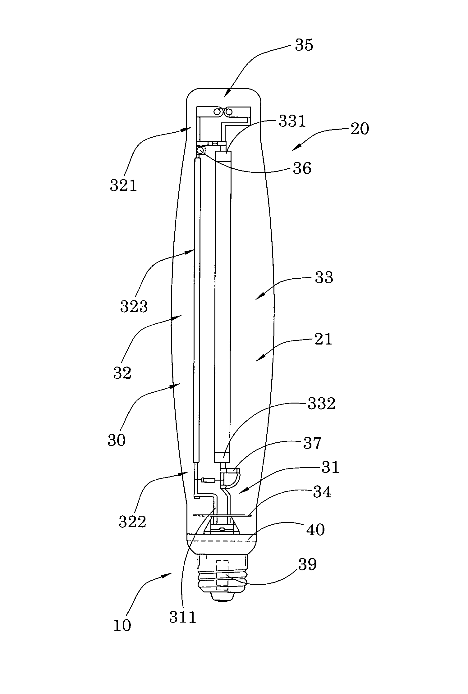
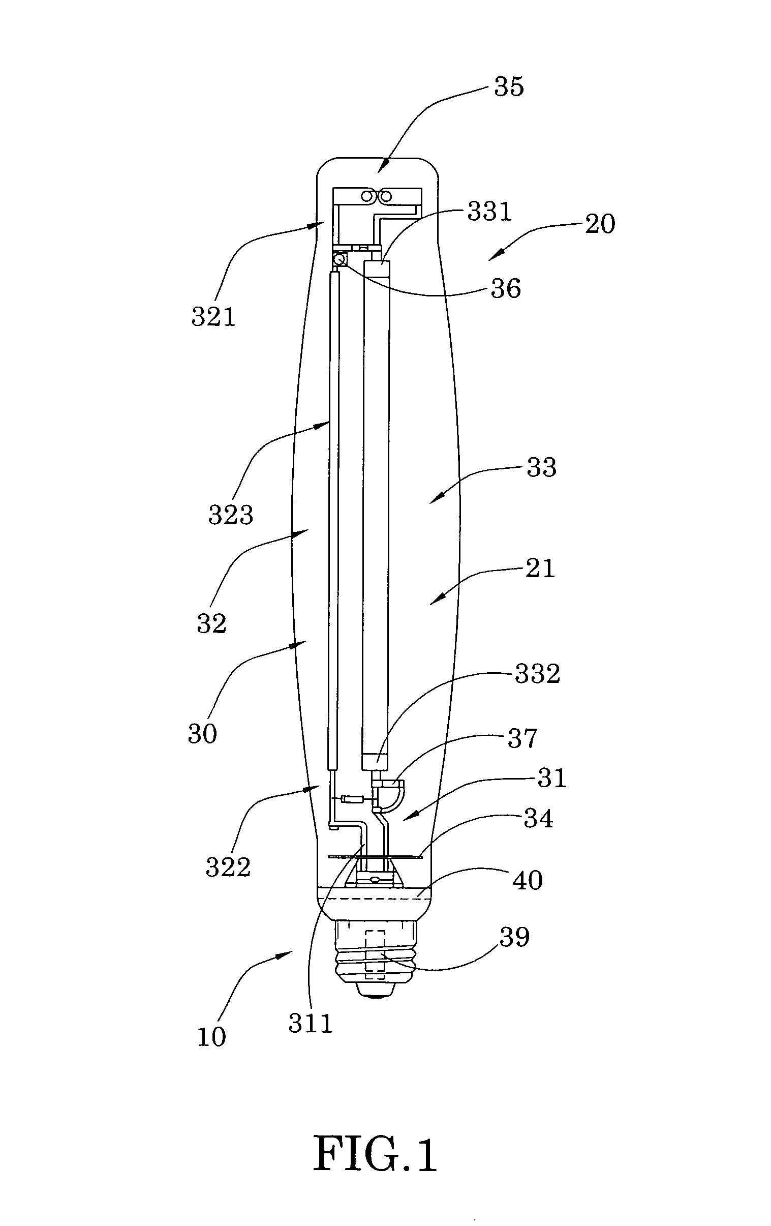
[0027]Referring to FIG. 1 to FIG. 5 of the drawings, a high pressure sodium lamp according to a preferred embodiment of the present invention is illustrated, in which the high pressure sodium lamp comprises a lamp base 10, a light admissible housing 20, and a sodium vapor illumination arrangement 30.

[0028]As shown in FIG. 1 of the drawings, the lamp base 10 is for electrically connecting to an external AC power source, and is threaded to allow a user to connect the high pressure sodium lamp to an external light socket.

[0029]The light admissible housing 20 is provided on the lamp base 10 and defines a lamp cavity 21 within the light admissible housing 20.

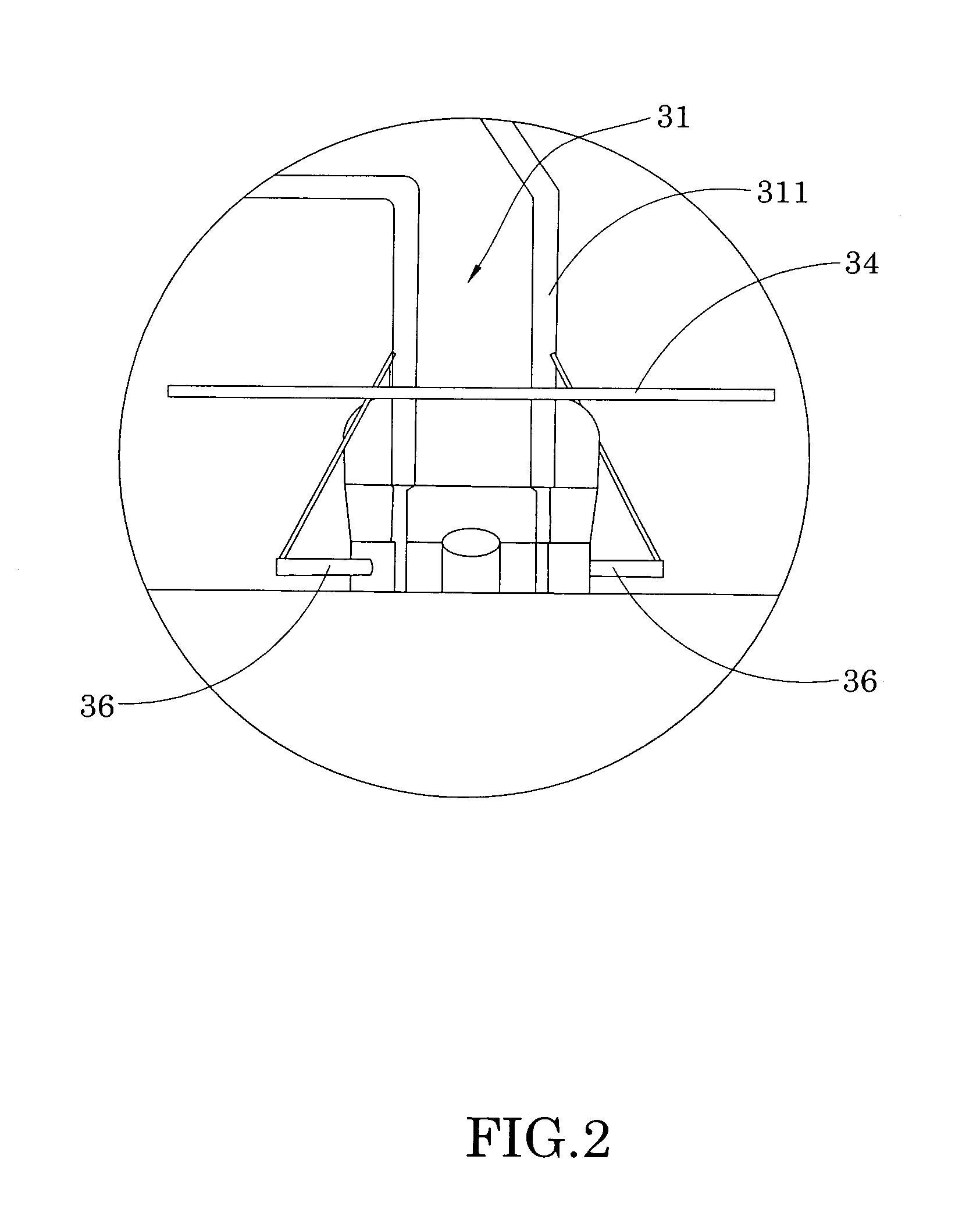
[0030]The sodium vapor illumination arrangement 30 comprises a light core 31, a supporting frame 32 and an arc tube 33 provided within the lamp cavity of the light admissible housing 20. On the other hand, the light core 31 extends from the lamp base 10 into the light admissible housing 20 and provides electricity connection from the...


PUM


Abstract

A high pressure sodium lamp includes a lamp base, a light admissible housing and a sodium vapor illumination arrangement, which includes a light core extended from the lamp base into the light admissible housing; a supporting frame, and an arc tube. The supporting frame longitudinally extends in the light admissible housing, and has an upper end portion supported by an upper portion of the light admissible housing, and a lower end portion supported by the light core. The arc tube has a first and a second electrode formed at two ends thereof and electrically connected with the upper end portion of the supporting frame and the light core respectively, wherein sodium vapor in the arc tube is electrically excited to discharge light having an intensity equivalent to that generated by more than 1000 W power.

Description

BACKGROUND OF THE PRESENT INVENTION[0001]1. Field of Invention[0002]The present invention relates to a lamp, and more particularly to a high pressure sodium lamp comprising a sodium vapor illumination arrangement which is capable of generating light which has more than 1500 W power.[0003]2. Description of Related Arts[0004]A conventional high pressure sodium lamp usually comprises a threaded head for externally connecting to a power source, a glass housing provided on the threaded head, and an arc tube mounted on the glass housing and filled with a predetermined amount of sodium vapor and / or other gases so that when the threaded head is electrically connected to the external power source, the sodium vapor in the arc tube is excited to generate illumination.[0005]This conventional high pressure sodium lamp has the established advantages of having high efficiency, low energy consumption, enhanced product life span and capable of providing high intensity illumination. Because of these ...

Claims


Application Information

Patent Timeline
Patent Type & Authority Patents(United States)
IPC IPC(8): H01J7/44H01J61/52H01J61/12
CPCH01J5/62H01J61/825
Inventor QIAN, FUQINGQIAN, SONG
Owner QIAN FUQING
Learn More