Otdm transmission method and apparatus

a transmission method and optical time division multiplexing technology, applied in multiplex communication, orthogonal multiplex, frequency-division multiplex, etc., can solve the problems of inactive use of dispersion compensation techniques, and achieve the effect of small tolerance to the fundamental dispersion of transmission fibers, good effect on pulse transmission characteristics, and sufficient toleran

Inactive Publication Date: 2007-05-17
JAPAN SCI & TECH CORP
View PDF9 Cites 7 Cited by
  • Summary
  • Abstract
  • Description
  • Claims
  • Application Information

AI Technical Summary

Benefits of technology

[0016] Because the ultrahigh-speed OTDM transmission uses very short pulses, the transmission system has a small tolerance to dispersion of the transmission fiber fundamentally. A small change in dispersion value has a great effect on the pulse transmission characteristics. In the transmission of very short pulses, consideration must be given to the effect of broadening of a pulse (polarization mode dispersion) caused by random changes in the polarization state of the transmission signal, induced by disturbances such as vibration and temperature variations. Accordingly, an adaptive equalization technique for dispersion and a polarization-mode dispersion compensation technique are required to ensure a sufficient tolerance to changes in the dispersion value and polarization mode dispersion. These dispersion compensation techniques have not yet been put into active use.

Problems solved by technology

These dispersion compensation techniques have not yet been put into active use.

Method used


Image

  • Otdm transmission method and apparatus
  • Otdm transmission method and apparatus
  • Otdm transmission method and apparatus

Examples


first embodiment

2. OTDM Transmission Apparatus of a First Embodiment

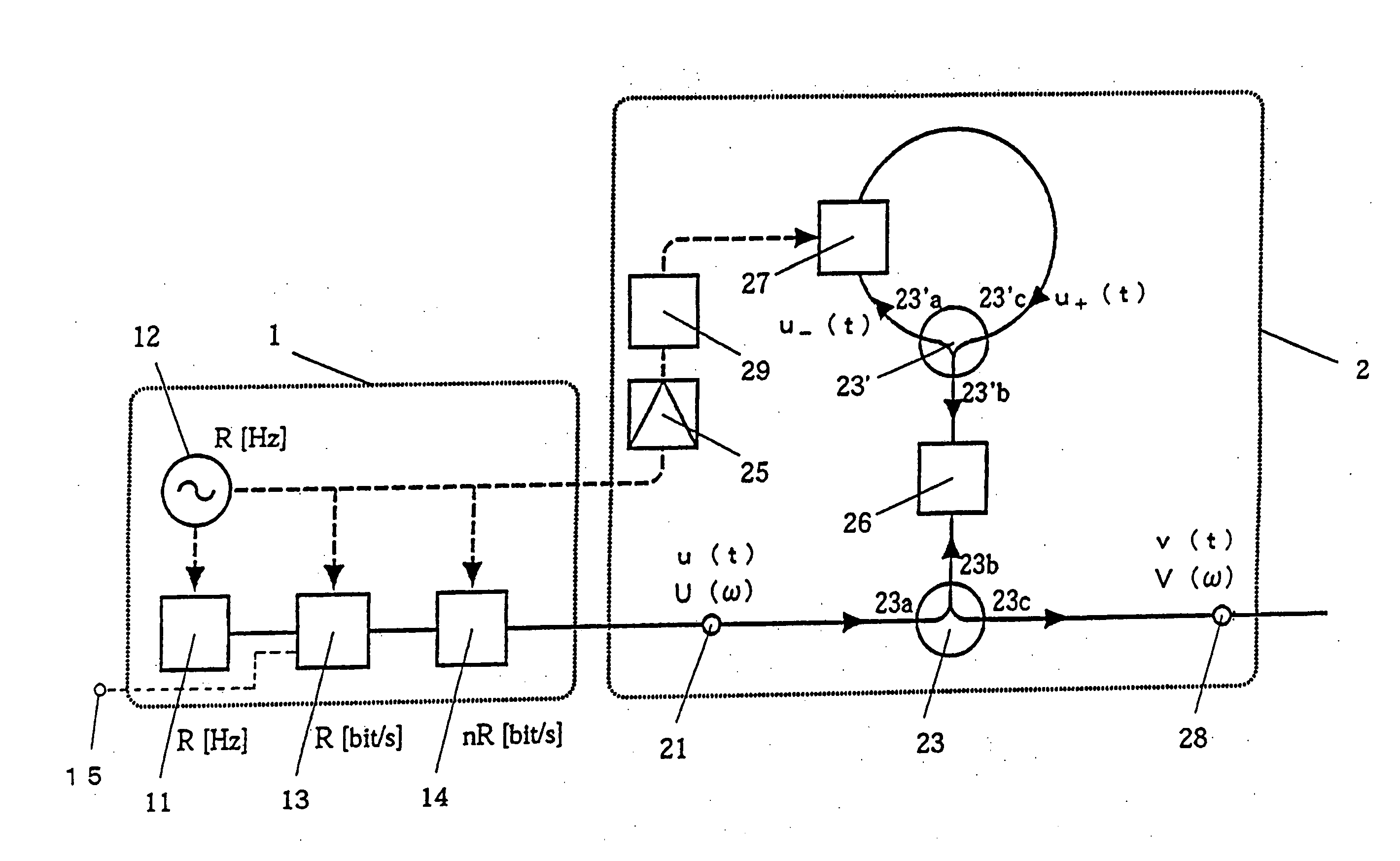
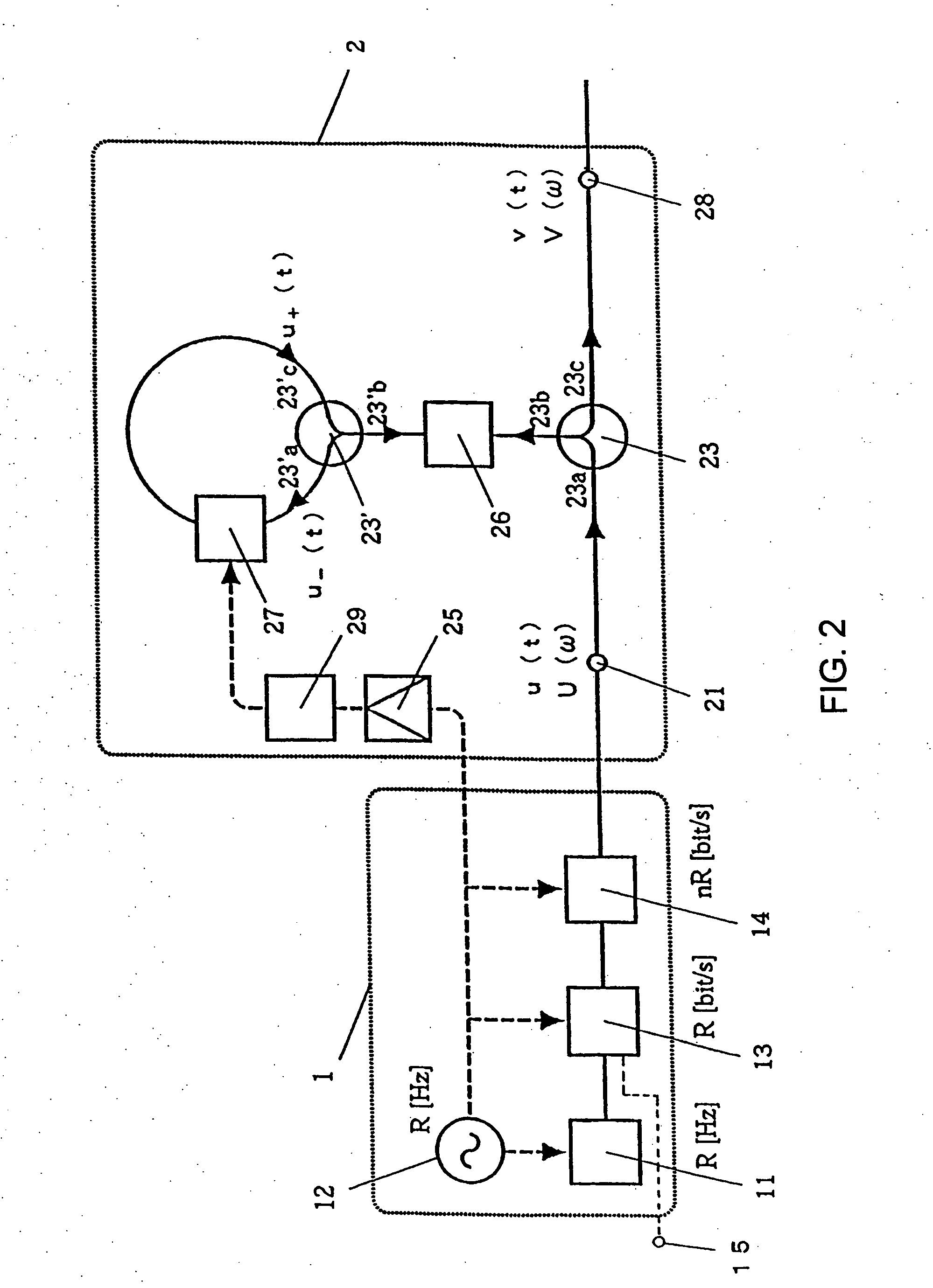
[0037]FIG. 2 shows the configuration of the OTDM signal transmitter 1 and the optical Fourier transform circuit 2 of a first embodiment.

[0038] As shown in FIG. 2, the OTDM signal transmitter 1 includes an optical pulse light source 11, a clock signal source 12, an optical modulator 13, an OTDM multiplexer 14, and a data input terminal 15. The optical pulse light source 11 operates at a frequency of R (Hz) supplied from the clock signal source 12. The optical modulator 13 is driven by the clock signal supplied from the clock signal source 12 and modulates an optical pulse train having a base repetition frequency of R (Hz) to an optical pulse signal sequence of a transmission rate of R (b / s) in accordance with transmission data input from the data input terminal 15. The OTDM multiplexer 14 is driven by the clock signal supplied from the clock signal source 12, and time-division-multiplexes the optical pulse signal sequences of n cha...

second embodiment

3. OTDM Transmission Apparatus of a Second Embodiment

[0062] By exchanging the dispersion element 26 and the phase modulator 27 in the optical Fourier transform circuit 2 shown in FIG. 2, a similar optical Fourier transform circuit can be implemented (see patent document 2).

[0063]FIG. 3 is a diagram showing the configuration of the OTDM signal transmitter 1 and an optical Fourier transform circuit 20 of a second embodiment. The OTDM signal transmitter 1 is the same as in the first embodiment.

[0064] The optical Fourier transform circuit 20 includes an input terminal 21, optical circulators 23 and 23′, an electric amplifier 25, a dispersion element 26, a phase modulator 27, an output terminal 28, a multiplier or divider 29, and an optical delay element 30. The phase modulator 27 is driven in accordance with a clock signal supplied from the clock signal source 12 through the electric amplifier 25 and the multiplier or divider 29, and a phase modulation is applied to the pulse train in...


PUM


Abstract

An OTDM transmitting method and transmitter realizing an OTDM distortion-free transmission substantially not relying upon dispersion. A time division multiplexed OTDM signal from an OTDM signal transmitter (1) enters an optical Fourier transform unit (2). Optical Fourier transform can be carried out most accurately so long as the optical pulse is a chirp-free Fourier transform limit pulse. The optical Fourier transform unit (2) converts the time waveform of the pulse into a signal on the frequency axis, and an optical inverse Fourier transform unit (2′) converts a spectral shape on the frequency axis into a time waveform (pulse). An optical fiber transmission line (3) is a transmission line having an arbitrary dispersion and a polarization mode dispersion. These dispersions may involve a time variation. An OTDM signal receiver (4) demultiplexes a transmission signal into low-speed optical signals, in a light region, receives optical pulses for respective channels and converts them into electric signals.

Description

TECHNICAL FIELD [0001] The present invention relates to optical time division multiplexing (OTDM) transmission methods and apparatuses, and more specifically, to an OTDM transmission method and apparatus for making it possible to remove all (or almost all) of the distortions due to dispersion or polarization-mode dispersion of the optical fiber transmission line from the time-domain waveform of a signal, the distortions having the potential for presenting a problem when the transmission rate of OTDM transmission increases. BACKGROUND ART [0002] In optical-fiber communication, time division multiplexing (TDM) and wavelength division multiplexing (WDM) are used as multiplexing techniques for increasing the number of signal channels served by a single fiber-optic line and making effective use of the line. Especially, a method known as optical time division multiplexing (OTDM) enables optical transmission at a rate higher than any electric processing speed, by dividing an optical pulse ...

Claims


Application Information

Patent Timeline
Patent Type & Authority Applications(United States)
IPC IPC(8): H04J11/00H04B10/2507H04B10/2519H04B10/2525H04B10/2569H04B10/516H04B10/61H04J1/00H04J3/00H04J14/08
CPCH04B10/503H04J14/08H04B10/2507H04B10/2581
Inventor HIROOKA, TOSHIHIKONAKAZAWA, MASATAKA
Owner JAPAN SCI & TECH CORP
Why Eureka
Try Eureka