
Antenna

a technology of antennas and antennas, applied in the field of antennas, can solve the problems of insufficient antenna gain, and achieve the effects of reducing impedance difference, reducing loss on matching circuits, and sufficient antenna gain

Inactive Publication Date: 2013-05-28
HONDA ACCESS CORP
View PDF3 Cites 4 Cited by
  • Summary
  • Abstract
  • Description
  • Claims
  • Application Information

AI Technical Summary

Benefits of technology

[0008]It is an object of the present invention to provide an antenna small in its size but capable of achieving sufficient antenna gain.
[0010]The antenna of the present invention can reduce impedance difference to be matched by a matching circuit by employing a short stub and an open stub, thereby making it possible to reduce the loss on the matching circuit and achieve sufficient antenna gain despite the size of the antenna being small.

Problems solved by technology

However, according to such conventional inverted-L antenna and inverted-F antenna, there are problems that sufficient antenna gain cannot be achieved when the height of the horizontal section is low, preventing radio waves from being emitted therefrom.

Method used


Image

  • Antenna
  • Antenna
  • Antenna

Examples


Embodiment Construction

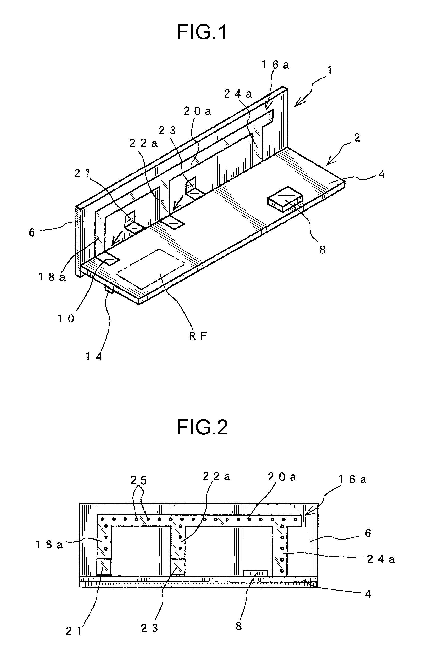
[0018]An embodiment of the present invention is described in detail hereunder with reference to the accompanying drawings. An antenna 1 according to the present embodiment is suitable for use in a wireless starting system 2 mounted on a vehicle or the like. As shown in FIG. 1, the wireless starting system 2 comprises a circuit board 4 and an antenna board 6.

[0019]Here, the wireless starting system 2 is a system that allows a driver to wirelessly lock or unlock the doors and tailgate, etc of a vehicle, and start the engine thereof by wirelessly matching an ID code between a receiving device disposed on the main body of the vehicle and a key called keyless operation key. The keyless operation key has a radio communication function, and the driver is only required to carry the keyless operation key and enter a wireless operation range of the vehicle in order to effect the matching of the aforementioned ID code (so-called keyless entry system). The antenna 1 is suitable for use not only...


PUM


Abstract

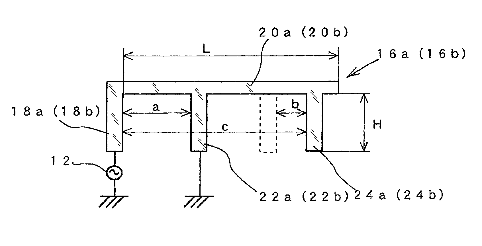
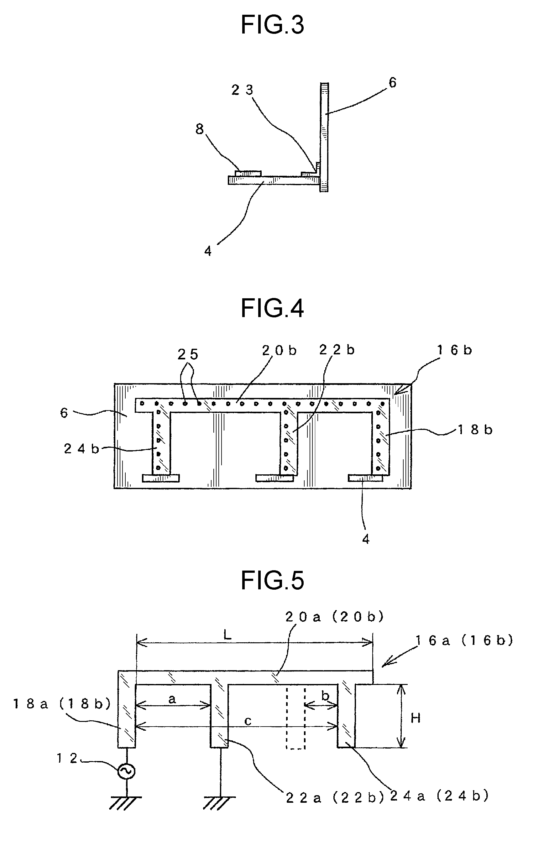
There is provided an antenna small in its size but capable of achieving sufficient gain. The antenna comprises antenna elements connected to a power source. The antenna elements comprise upstanding vertical sections connected to the power source and horizontal sections substantially parallel with a ground pattern and having one end thereof connected to an end portion of the vertical sections. The antenna elements further comprise short stubs provided away from the vertical sections toward the other end of the horizontal sections and connected to the ground pattern, and open-ended open stubs provided away from the short stubs toward the other end of the horizontal sections and extending from the horizontal sections toward the ground pattern. The antenna elements are made of a metal foil and are provided on an antenna board.

Description

BACKGROUND OF THE INVENTION[0001]1. Field of the Invention[0002]The present invention relates to an antenna suitable for use in radio communication of a wireless starting system or the like for a vehicle.[0003]2. Description of Related Art[0004]Conventionally, an antenna employing a monopole antenna has been used for performing radio communication of a wireless starting system or the like for a vehicle. However, since such monopole antenna as a whole tends to be long in one direction, there has been provided a small-sized inverted-L antenna manufactured by bending the monopole antenna.[0005]In such inverted-L antenna, a capacitive reactance component is generated between a ground surface of a circuit board and a horizontal section of an antenna element parallel with the ground surface. When the height of the horizontal section of such inverted-L antenna is low, the impedance of the antenna decreases, thereby causing the impedance difference to be matched to increase, thus making it ...

Claims


Application Information

Patent Timeline
Patent Type & Authority Patents(United States)
IPC IPC(8): H01Q1/38
CPCH01Q1/32H01Q9/42H01Q1/38
Inventor SAKAI, HIROTO
Owner HONDA ACCESS CORP
Learn More