

Coaxial pumping apparatus with internal power fluid column
a technology of power fluid column and coaxial pump, which is applied in the field of pumps, can solve the problems of 85% maintenance costs account for approximately 10% of the total cost of operating a conventional pump, so as to reduce the number of moving parts, increase energy efficiency, and reduce maintenance costs
Active Publication Date: 2013-06-04
MCNICHOL RICHARD F
View PDF28 Cites 8 Cited by
- Summary
- Abstract
- Description
- Claims
- Application Information
AI Technical Summary
Benefits of technology
The design enhances energy efficiency and reduces maintenance costs by optimizing fluid transfer and minimizing particle damage, leading to lower operational expenses and improved performance in energy-intensive applications.
Problems solved by technology
It has been estimated that approximately 85% of the total cost of operating a conventional pump is attributable to energy consumption.
Similarly, maintenance costs account for approximately 10% of the total cost of operating a conventional pump.
Method used
View moreImage
Smart ImageViewing Examples

Examples
example 1
[0324]for a=0.1; and r=0.8
[0325]Eff=100r(1+a)(1-a)+(a-(1-r))(1+a),=801.10.9+(0.1-0.2)1.1,=801.22-0.11.1,=801.22-0.091,Eff=70.9%
example 2
[0326]for a=0.1; and r=0.5
[0327]Eff=100r(1+a)(1-a)+(a-(1-r))(1+a)=501.10.9+(0.1-0.5)1.1=501.22-0.41.1=501.22-0.364Eff=58.4%
example 3
[0328]for a=0.01; and r=0.8
[0329]Eff=100r(1+a)(1-a)+(a-(1-r))(1+a)=801.010.99+(0.01-0.2)1.01=801.22-0.191.01=801.22-0.188Eff=71.4%
Login to View More PUM
 Abstract
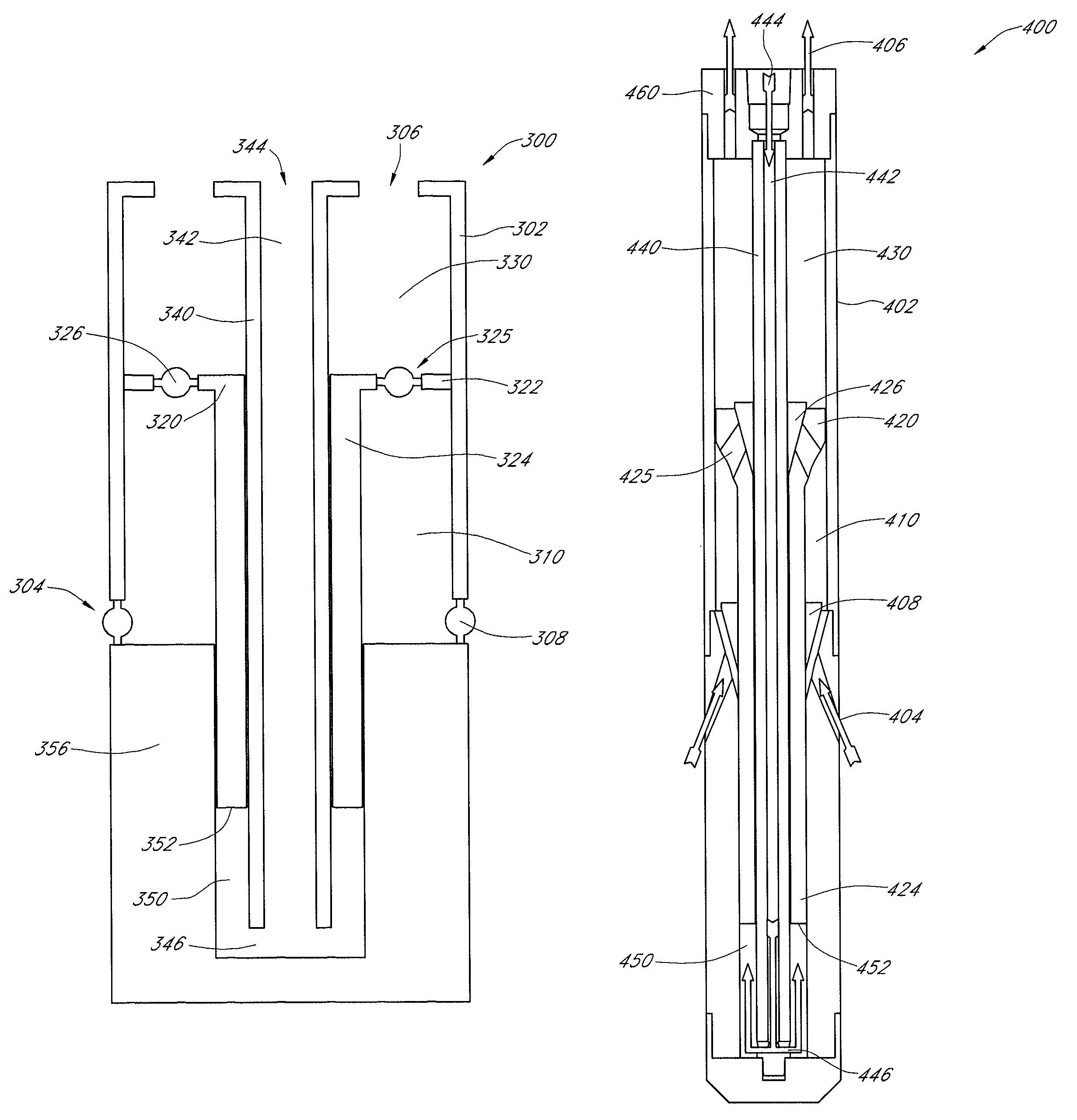
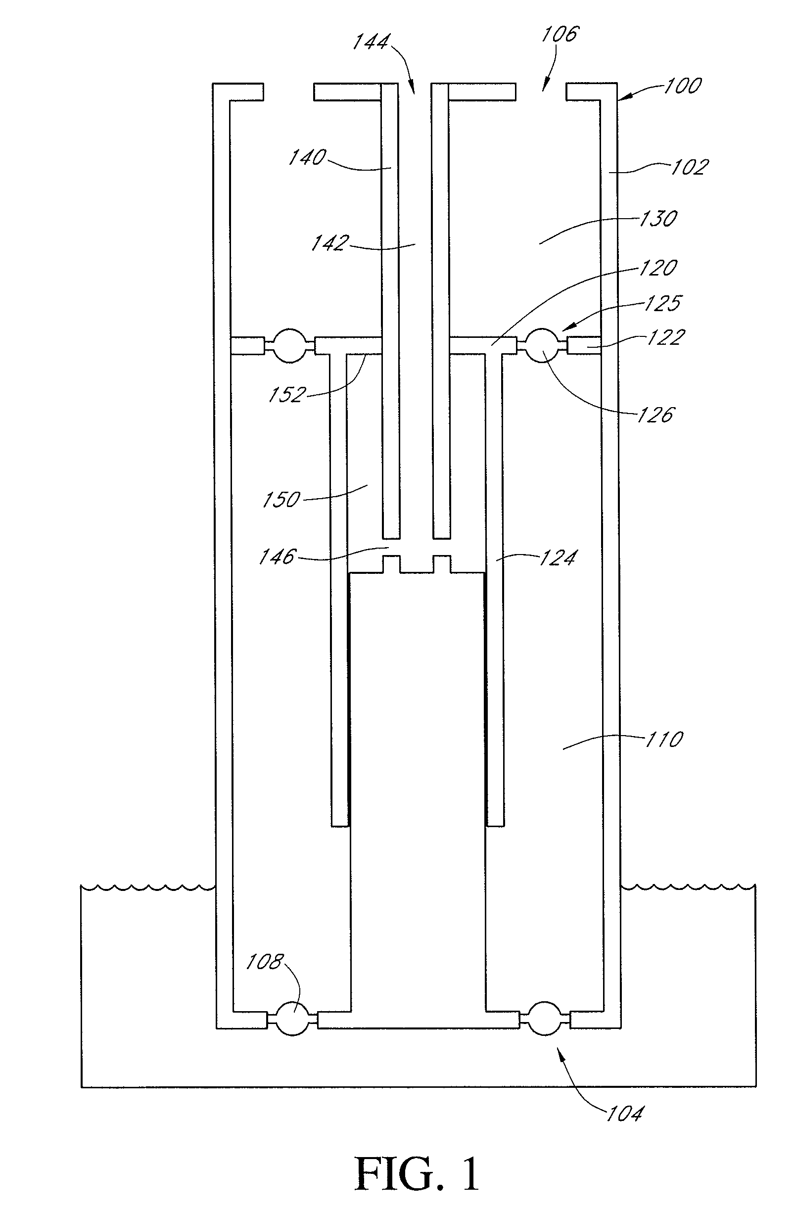
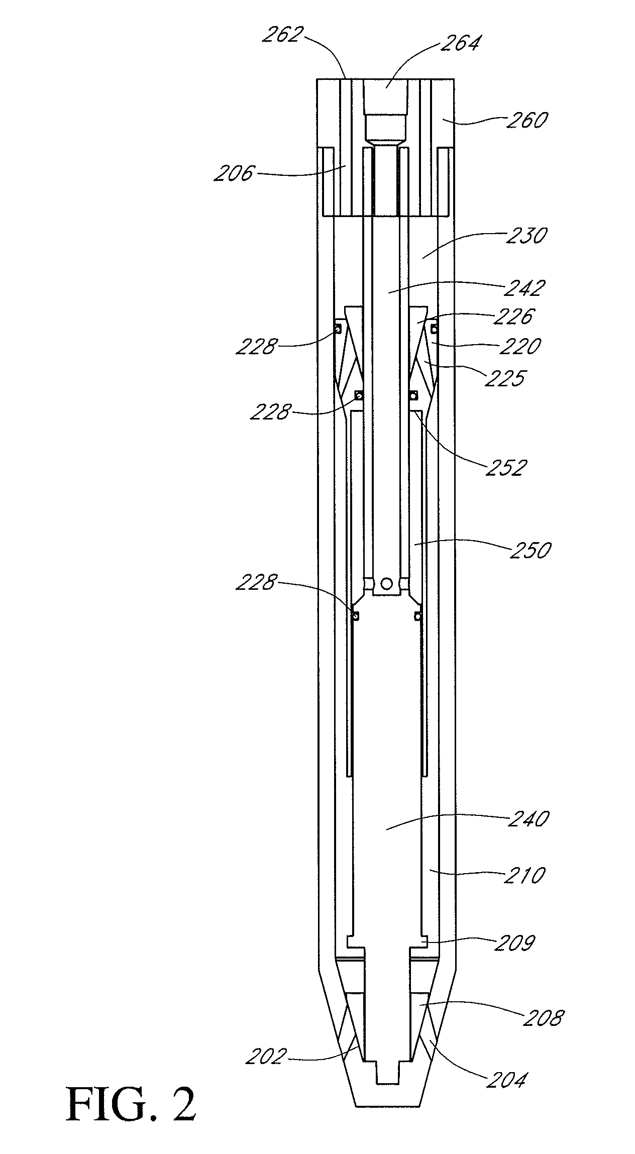
A pump having an increased energy efficiency is provided. The pump has an internal power fluid column and a transfer piston which is reciprocatingly mounted about the power fluid column. The transfer piston defines a product fluid chamber, located above the transfer piston valve, and a transfer chamber, located below the transfer piston valve. The power fluid column has at least one passageway, which allows the fluid inside the power fluid column to be in communication with a power fluid chamber. The power fluid chamber, the transfer chamber, and the product chamber are situated coaxially about the power fluid column.
Description
CROSS-REFERENCE TO RELATED APPLICATIONS[0001]This application claims the benefit under 35 U.S.C. §119(e) of U.S. provisional application Ser. No. 60 / 898,377, filed Jan. 30, 2007, the disclosure of which is hereby expressly incorporated by reference in its entirety and is hereby expressly made a portion of this application.FIELD OF THE INVENTION[0002]The present application relates generally to pumps, and more particularly to piston type pumps having increased energy efficiency, systems incorporating such piston type pumps, and methods of operating piston type pumps.BACKGROUND OF THE INVENTION[0003]It has been estimated that approximately 85% of the total cost of operating a conventional pump is attributable to energy consumption. Moreover, pumping systems account for nearly 20% of the world's electrical energy demand and range from 25% to 50% of the energy required by industrial plant operations.[0004]Similarly, maintenance costs account for approximately 10% of the total cost of op...
Claims
Login to View More Application Information
Patent Timeline
 Patent Type & Authority Patents(United States)
IPC IPC(8): F04B35/02F04B9/107
CPCF04B47/08F04B9/1056F04B19/22F04B53/12F04B53/14F04B53/16
Inventor FISHER, NORMMCNICHOL, RICHARD FREDERICK
Owner MCNICHOL RICHARD F