
Electrophysiology ablation device

a technology of electrophysiology and ablation device, which is applied in the field of electrophysiology ablation device and medical appliances, can solve the problems of abnormal heart rhythm, inability to carry out ideal circumferential ablation of the orifice of the pulmonary vein, and inability to carry out ideal circumferential ablation

Active Publication Date: 2013-06-04
BEIJING AMSINO MEDICAL
View PDF16 Cites 23 Cited by
  • Summary
  • Abstract
  • Description
  • Claims
  • Application Information

AI Technical Summary

Benefits of technology

[0005]One objective of the present invention is to provide an electrophysiology ablation device that makes possible precise positioning of the ablation electrode at the orifice of the pulmonary vein to carry out precise and ideal circumferential ablation.
[0014]In the present invention, a guiding ring is provided at a front end of the catheter sleeve, and a guiding steel wire is inserted through the catheter sleeve with a front end thereof connected to the guiding ring, wherein the direction for which the catheter head is heading can be controlled by the guiding steel wire, so as to make it convenient for the catheter head to pass through the blood vessel.
[0015]In the present invention, the guiding ball is opaque under Roentgen ray, thus facilitating observation of the position of the guiding ball during a surgical operation.
[0016]In the present invention, the guiding ball is coated with an anticoagulation coating to avoid formation of thrombus due to long duration of the surgical operation.
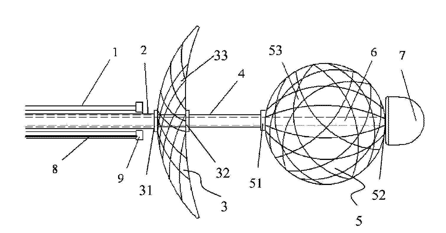
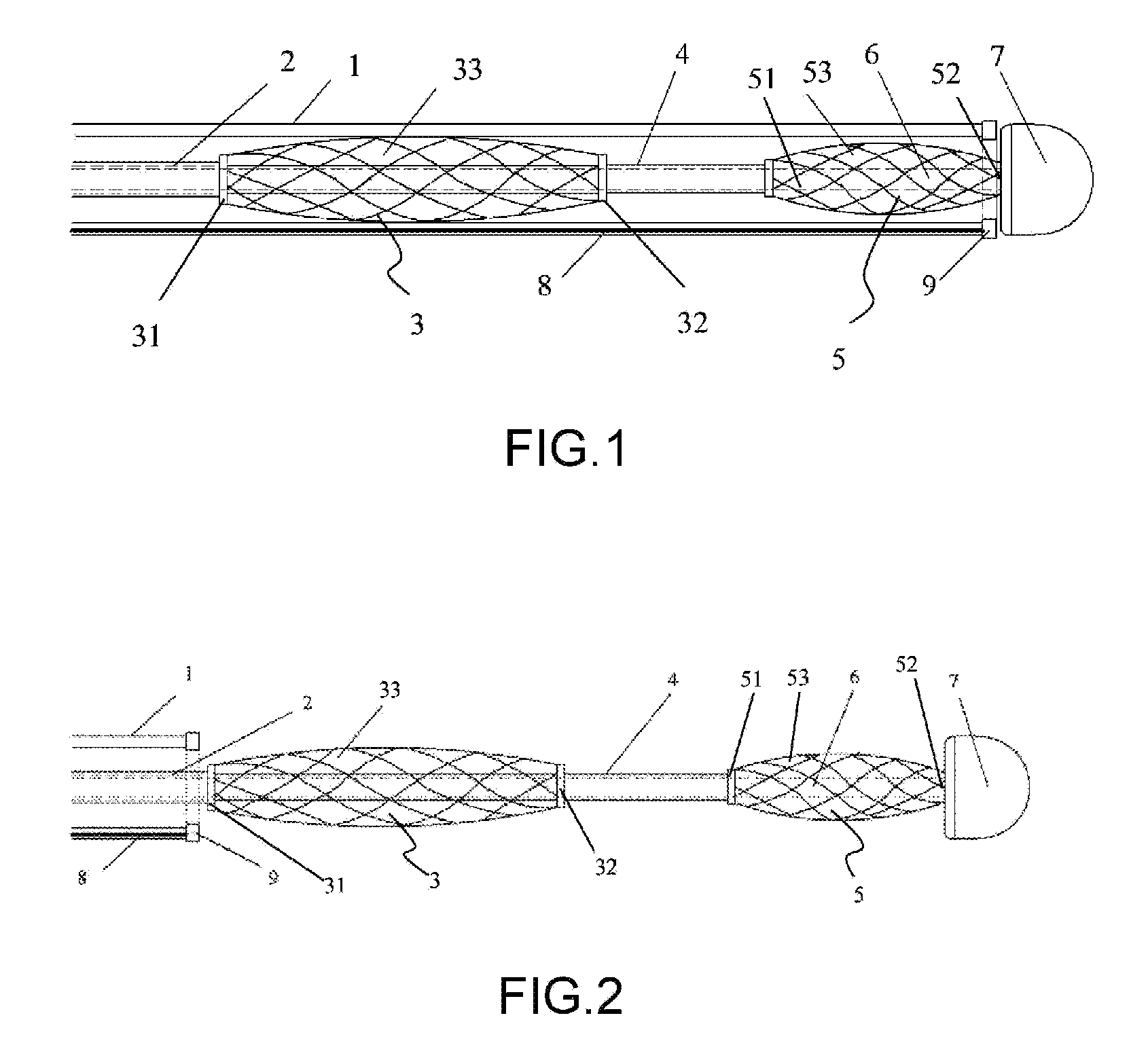
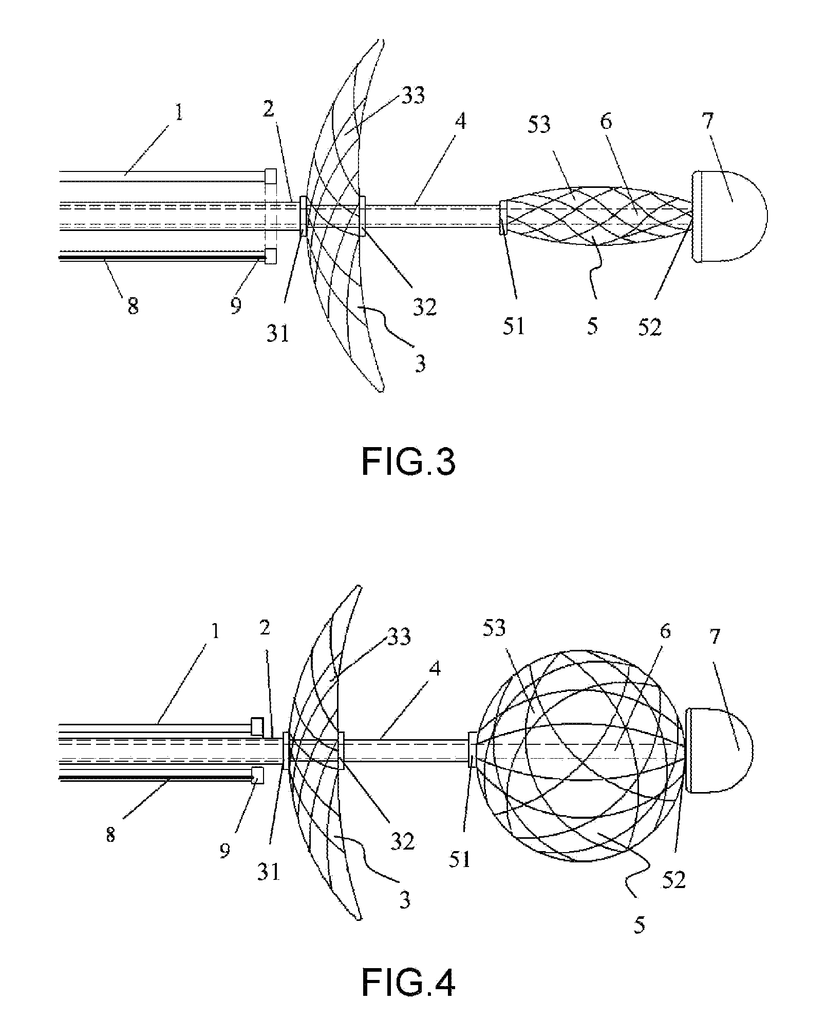
[0019]By employment of the electrophysiology ablation device according to the present invention, when the catheter reaches the left atrium, the guiding ball and the ablation electrode are sequentially deployed through adjustment of the relative positions of the electrode sleeve, the guiding ball sleeve and the central rod. Since the guiding ball is of a spherical shape and the spherical center is located on the central axis of the disk ablation electrode, the guiding ball more easily slides into the orifice of the pulmonary vein on contact with a peripheral area of the orifice of the pulmonary vein than a common catheter head does, and guides the electrophysiology catheter and the ablation electrode in form of a meshed bowl-like disk to enter the pulmonary vein to thereby help the surgeon more quickly determine the position of the orifice of the pulmonary vein. After the guiding ball enters the orifice of the pulmonary vein, since the circle centers of the guiding ball and the ablation electrode in form of a meshed bowl-like disk are located on the same central axis, and since the diameter of the guiding ball is substantially equal to the diameter of the pulmonary vein, jittering of the electrophysiology catheter in the pulmonary vein can be reduced, and the edge of the meshed bowl-like ablation electrode can be more compactly abutted against the orifice of the pulmonary vein than that of a conventional flat ablation electrode, thereby achieving precise and ideal circumferential ablation once the power is turned on. After ablation, the meshed bowl-like disk ablation electrode serves as a mapping electrode to collect electrical signals coming from the ablated site to map the ablation effect.

Problems solved by technology

However, the advance in age or the change in pathological and physiological characteristics of the heart causes contraction disorder and abnormal rhythm of the heart.
That invention is mainly defective in the following aspect: due to the difference in sizes and shapes of the orifices of the patients' pulmonary veins, it is very difficult in practical operation to abut the meshed flat disk completely against the orifice of the pulmonary vein, but instead usually only in a slanting or partial manner, so that it is impossible to carry out ideal circumferential ablation of the orifice of the pulmonary vein, and adversely affecting the therapeutic effect.

Method used


Image

  • Electrophysiology ablation device
  • Electrophysiology ablation device
  • Electrophysiology ablation device

Examples


Embodiment Construction

[0026]As shown in FIGS. 1-5, the electrophysiology ablation device according to the present invention comprises such components as a catheter sleeve 1, an electrically conductive electrode sleeve 2, a guiding ball sleeve 4, a central rod 6, an ablation electrode 3, and a guiding ball 5. The electrode sleeve 2 is made of an electrically conductive material and sheathed inside the catheter sleeve 1, the guiding ball sleeve 4 is sheathed inside the electrode sleeve 2, and the central rod 6 is sheathed inside the guiding ball sleeve 4. The catheter sleeve 1, the electrically conductive electrode sleeve 2, the guiding ball sleeve 4 and the central rod 6 are coaxially sheathed together to form the catheter structure, and the catheter sleeve 1, the electrically conductive electrode sleeve 2, the guiding ball sleeve 4 and the central rod 6 are axially moveable relative to one another. The relative axial movement can be relative axial sliding movement amongst these components.

[0027]One end 3...


PUM


Abstract

An electrophysiology ablation device includes a catheter sleeve (1), an electrode sleeve (2), a steering ball sleeve (4), a central rod (6), an ablation electrode (3) and a steering ball (5). The catheter sleeve (1), the electrode sleeve (2), the steering ball sleeve (4) and the central rod (6) are muff-coupled together, and the steering ball (5) can be deployed radially to define a meshed spherical shape, in order to steer the positioning of the ablation electrode (3) which can be deployed to define a meshed disk shape, so the ablation electrode (3) can be positioned at the ostium of the pulmonary vein accurately.

Description

CROSS REFERENCE TO RELATED APPLICATIONS[0001]The present application is the U.S. National Stage of International Application No. PCT / CN2007 / 070451, filed Aug. 10, 2007.FIELD OF THE INVENTION[0002]The present invention relates to electrophysiologically therapeutic device for the treatment of arrhythmia in the field of medical appliances, and more particularly, to an electrophysiology ablation device.BACKGROUND OF THE RELATED ART[0003]The heart is a complicated organ. Stimulation by heart current causes myocardial contraction to pump out blood and makes the blood to circulate in the blood vessel. The heart current passes through the atrium and then the ventricle to cause myocardial contraction. The myocardium rhythmically contracts under the action of heart current. However, the advance in age or the change in pathological and physiological characteristics of the heart causes contraction disorder and abnormal rhythm of the heart. One of the methods to treat arrhythmia is septal ablati...

Claims


Application Information

Patent Timeline
Patent Type & Authority Patents(United States)
IPC IPC(8): A61B18/14
CPCA61B18/1492A61N1/06A61B2018/00214A61B2018/00267A61B2018/00351A61B2018/00357A61B2018/00577A61B2018/1475A61N1/05
Inventor MA, XIAOYIHUANG, CONGXINLI, ZHENGYANG
Owner BEIJING AMSINO MEDICAL
Learn More