Developing cartridge, image forming apparatus, and method of mounting/demounting developing cartridge to/from image forming apparatus

a development cartridge and development cartridge technology, applied in the field of developing cartridges and image forming apparatuses, can solve the problems of affecting image quality, less frequent replacement of housing units, and high maintenance costs

Inactive Publication Date: 2013-06-04
HEWLETT PACKARD DEV CO LP
View PDF6 Cites 0 Cited by
  • Summary
  • Abstract
  • Description
  • Claims
  • Application Information

AI Technical Summary

Benefits of technology

[0018]The present general inventive concept provides a developing unit with improved structure to release a safety device to prevent damages to inner components thereof upon mounting the developing unit to an image forming apparatus, and an image forming apparatus having the same.
[0019]The present general inventive concept also provides a developing unit with improved structure to switch on or off components such as an optical scanning device that are potentially dangerous to users upon mounting to an image forming apparatus, and an image forming apparatus having the same.
[0043]A user does not have to remove a safety device to form a developing gap, because a developing gap is automatically created between a photoconductive medium and a developing member in accordance with mounting of the developing unit to an image forming apparatus.
[0044]Furthermore, product safety is enhanced because power supplied to an optical scanning device is automatically blocked in accordance with demounting of a developing unit. Thus, a user is protected even if the optical scanning device malfunctions.
[0047]The foregoing and / or other aspects and utilities of the general inventive concept may also be achieved by providing a method of changing a developing unit of an image forming apparatus, the method including moving at least one of a plurality of frames respectively supporting a photoconductive medium and a developing member of a developing unit with respect to each other between a first position and a second position based on one of a mounting state and a demounting state of the developing unit, and engaging a safety switch to prevent a user from receiving unwanted radiation based on whether the plurality of frames are in the first position or the second position.

Problems solved by technology

Because the image forming apparatuses for office use are required to output far more printouts than printouts for home use, maintenance will cost a lot if the image forming apparatuses for office use employ the developing cartridges and the developing units as a set.
Thus, replacement of the housing unit is less frequent and occurs when the photoconductive medium is too old to react to light exposure, or when image quality degrades severely.
However, problems occur when the photoconductive medium 10 is maintained in contact with the developing gap maintaining discs 30.
First, an unexpected impact may be exerted to the developing unit when the developing unit is moved or operated, subsequently causing physical damage to the developing gap maintaining discs 30.
Subsequently, the damaged developing gap maintaining discs 30 do not maintain the desired developing gaps, and as a result, image quality degradations such as creasing occur.
However, most of the printer users are not familiar with detailed structure of the components.
Furthermore, a requirement for the removal of the rubber pin 1b before mounting the developing unit is inconvenient for the user.

Method used


Image

  • Developing cartridge, image forming apparatus, and method of mounting/demounting developing cartridge to/from image forming apparatus
  • Developing cartridge, image forming apparatus, and method of mounting/demounting developing cartridge to/from image forming apparatus
  • Developing cartridge, image forming apparatus, and method of mounting/demounting developing cartridge to/from image forming apparatus

Examples


Embodiment Construction

[0059]Reference will now be made in detail to embodiments of the present general inventive concept, examples of which are illustrated in the accompanying drawings, wherein like reference numerals refer to the like elements throughout. The embodiments are described below in order to explain the present general inventive concept by referring to the figures.

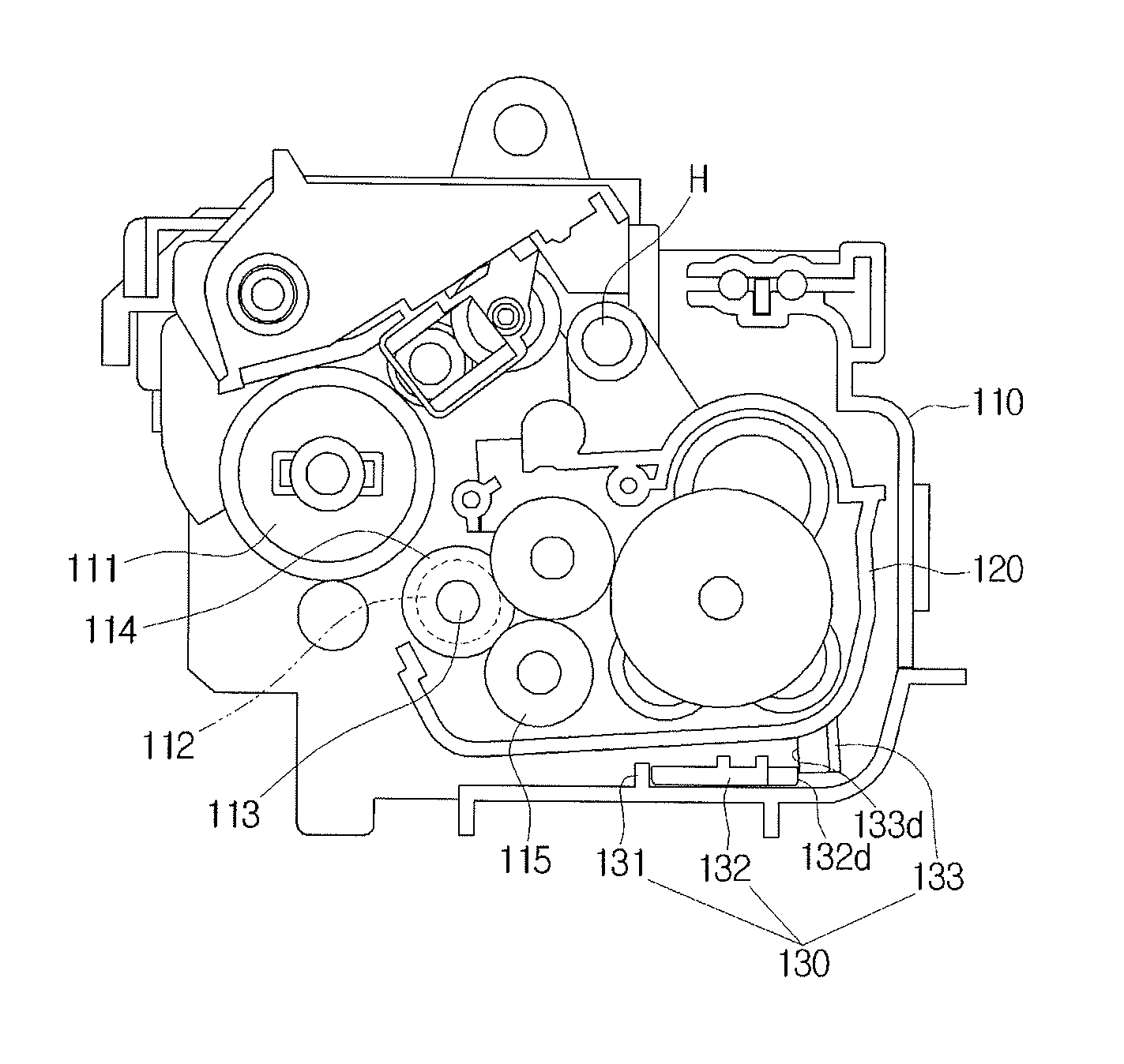
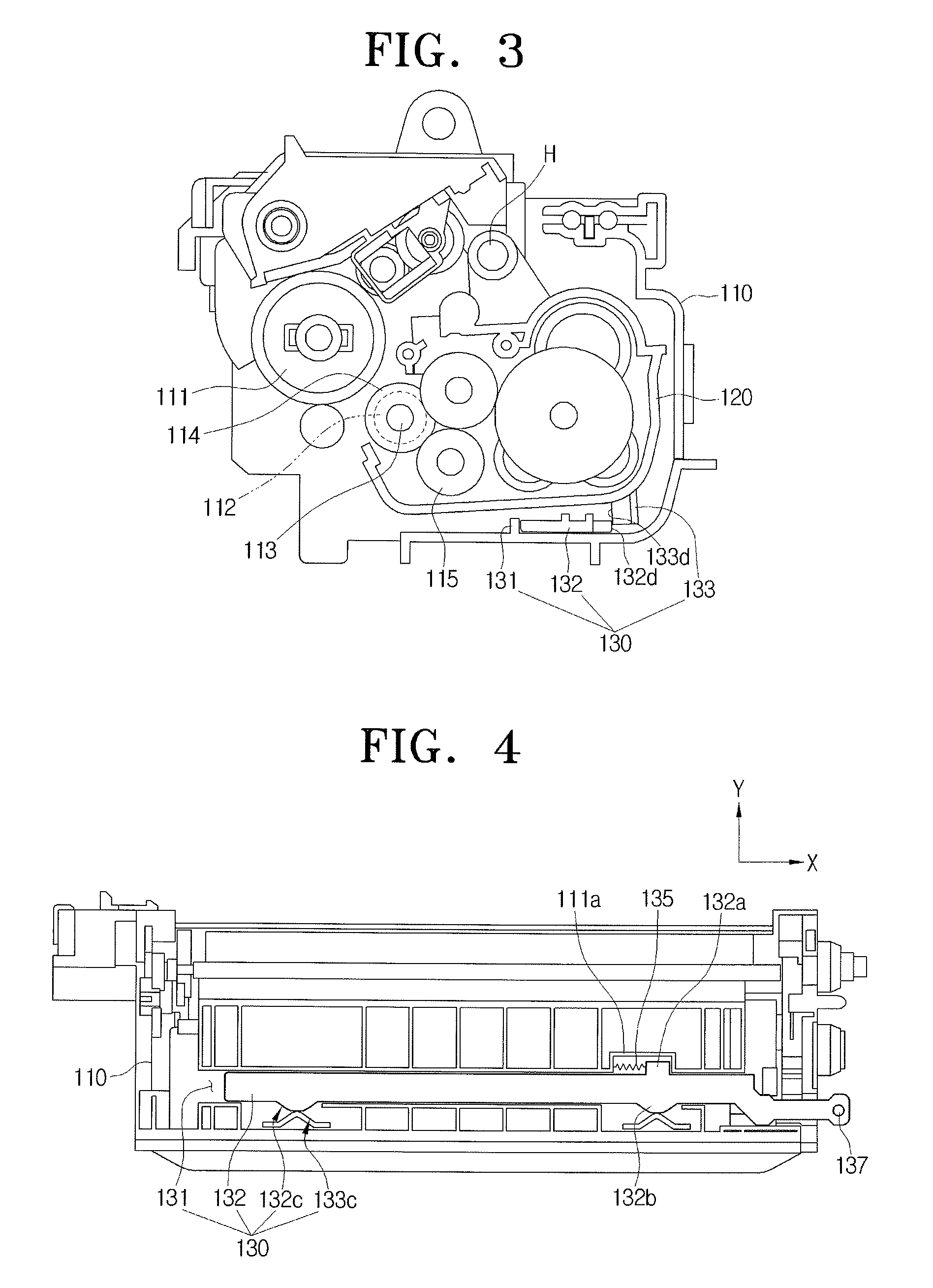
[0060]FIGS. 3 and 4 illustrate a developing unit before mounting to an image forming apparatus according to an exemplary embodiment of the present general inventive concept.

[0061]Referring to FIGS. 3 and 4, the developing unit includes a first frame 110, a second frame 120 turnable about a hinge point H of the first frame 110, and a positioning unit 130 to change a position of the second frame 120.

[0062]The first frame includes a photoconductive medium 111 rotatably disposed thereon, and the second frame 120 includes a developing member 112 and a feeding member 115 disposed thereon to supply the developer to the photoconductive medi...


PUM


Abstract

A developing unit usable with an image forming apparatus includes a first frame to support a photoconductive medium, a second frame to support a developing member to apply a developer to the photoconductive medium, the second frame movable between a first position in which the photoconductive medium is at a developing gap from the developing member, and a second position in which the photoconductive medium is away from the developing member by a distance exceeding the developing gap, and a positioning unit to move the second frame from a current position in accordance with mounting and demounting of the developing unit to and from the image forming apparatus.

Description

CROSS-REFERENCE TO RELATED APPLICATIONS[0001]This application claims priority under 35 U.S.C. §119(a) from Korean Patent Application No. 2007-98106, filed Sep. 28, 2007, in the Korean Intellectual Property Office, the disclosure of which is hereby incorporated in its entirety by reference.BACKGROUND OF THE INVENTION[0002]1. Field of the Invention[0003]The present general inventive concept relates to an image forming apparatus, and more particularly, to a developing unit removably mounted to an image forming apparatus, and an image forming apparatus having the same.[0004]2. Description of the Related Art[0005]Generally, an image forming apparatus includes a paper feed unit, a developing unit, a transfer unit, a fusing unit, and a paper discharge unit.[0006]Most of the developing units employed in image forming apparatuses for home use are formed as a single body with the developer cartridges, while most of the developing units for office use are separately provided. Because the image...

Claims


Application Information

Patent Timeline
Patent Type & Authority Patents(United States)
IPC IPC(8): G03G15/00G03G21/18G03G15/04
CPCG03G21/1825G03G15/00G03G15/06
Inventor CHEON, YONG-JUNOH, JOO-HWAN
Owner HEWLETT PACKARD DEV CO LP
Why Eureka
Try Eureka