
Bistable magnetic actuators

a magnetic actuator and actuator technology, applied in the direction of magnets, relays, magnetic bodies, etc., can solve the problem of additional reducing the magnetic resistance compared to known arrangements with built-up u-shaped, and achieve the effects of low magnetic resistance, high coercivity, and high remanen

Active Publication Date: 2013-06-11
JOHNSON ELECTRIC DRESDEN
View PDF20 Cites 47 Cited by
  • Summary
  • Abstract
  • Description
  • Claims
  • Application Information

AI Technical Summary

Benefits of technology

The patent describes a design for an electrical motor that has two parallel magnetic circuits with very low magnetic resistance. This is achieved by using a flat permanent magnet and a one-part U-shaped yoke design, which reduces the magnetic resistance compared to traditional arrangements. The motor also has a rocking armature bearing that works efficiently on metallic surfaces due to the low magnetic resistance. The technical effect of this design is a more efficient and reliable electrical motor.

Problems solved by technology

The U-shaped yoke with its two outer legs is made one-part, which additionally reduces the magnetic resistance compared to known arrangements with a built-up U-shaped yoke.

Method used


Image

  • Bistable magnetic actuators
  • Bistable magnetic actuators
  • Bistable magnetic actuators

Examples


Embodiment Construction

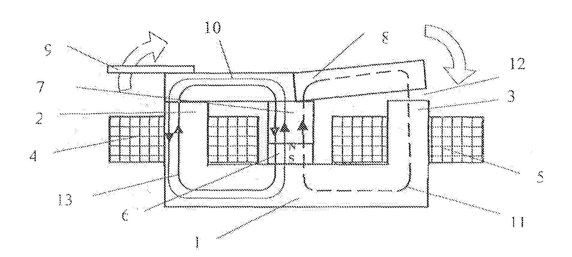
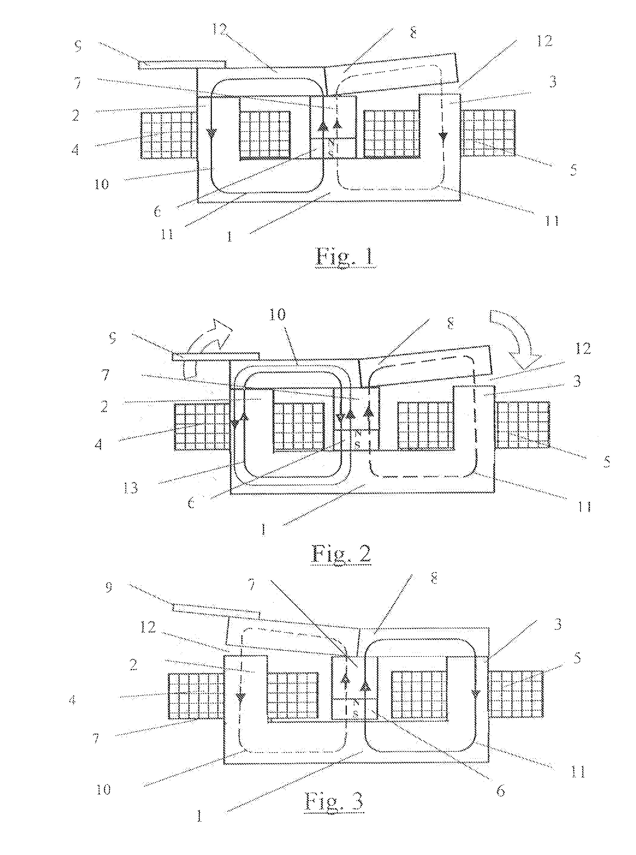
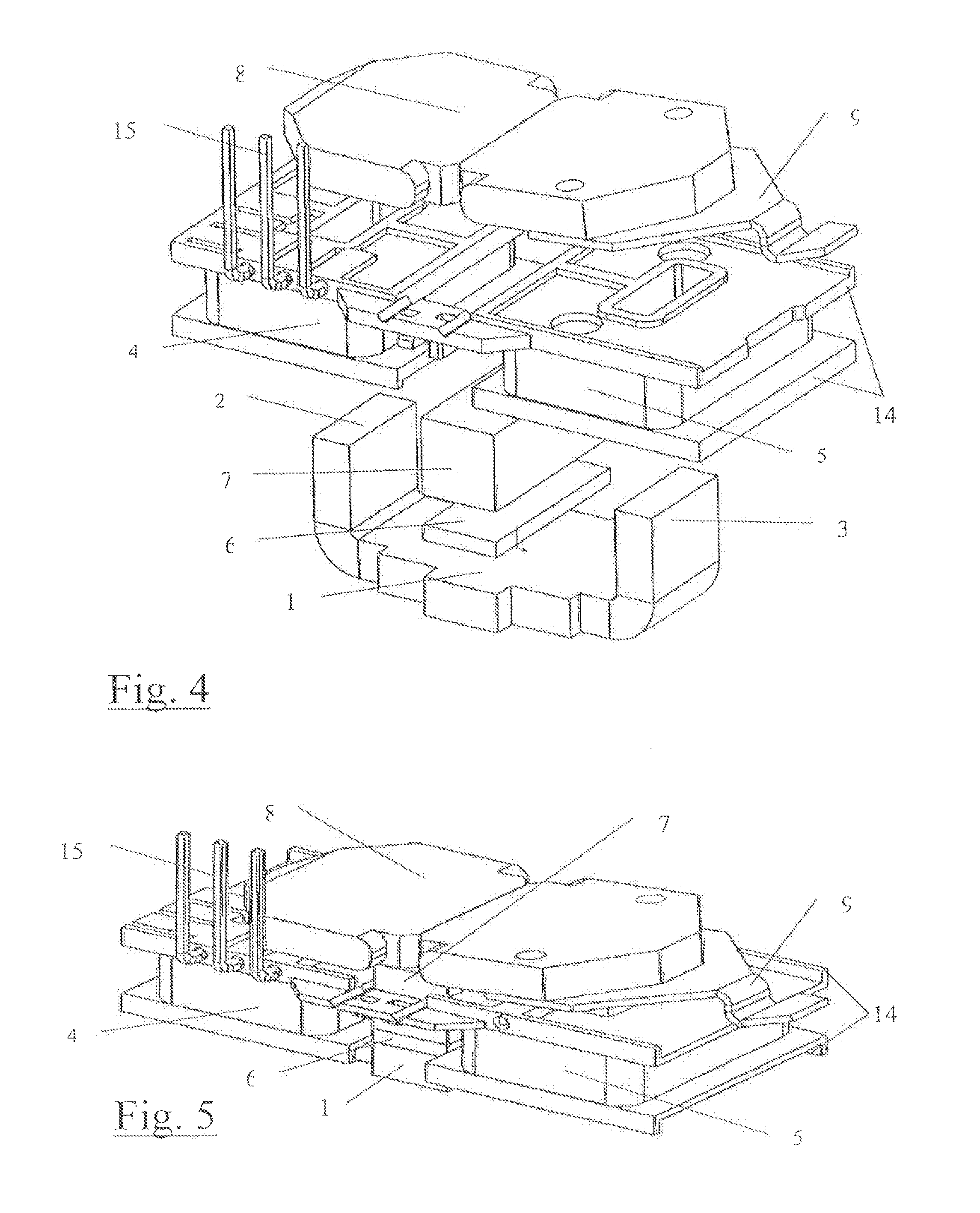
[0016]In the FIGS. 1 to 3 the operational mode of a magnetic actuator is schematically shown. The actuator has as a carrying part a U-shaped soft-iron yoke 1 with separately controllable excitation windings 4, 5 placed on the outer legs 2, 3 of the yoke 1. An extremely flat but strong permanent magnet 6 supports a soft-iron centre leg 7. Thus an E-shaped magnet core is formed. A rocking armature 8 slightly bent in V-shape is supported at the centre leg 7. The E-shaped magnet core together with the rocking armature 8 starting from the centre leg 7 is a parallel circuit of the armature air gaps. At one end the rocking armature 8 carries an actuating member 9 for a contact system, for example, of a bipolar relay. In the position of the rocking armature 8 shown in FIGS. 1 and 2 a permanent-magnetic flux 10 forms in the left parallel circuit over the permanent magnet 6, the soft-iron centre leg 7, the left wing of the rocking armature 8, the left soft-iron centre leg 2, the yoke 1 and ba...


PUM


Abstract

In a bistable magnetic actuator with a polarized magnetic circuit with parallel operating air gaps, wherein between the outer legs of a U-shaped soft-iron yoke a flat permanent magnet is integrated that carries a soft-iron center leg and applies a permanent-magnetically created magnetic flux to a rocking armature supported on the center leg, wherein at each outer leg a separately controllable excitation winding provides swiveling pulses for the rocking armature to swivel from one permanent-magnetically self-holding swivel position into the other, the permanent-magnetically created magnetic flux through the magnetic circuit closed over the rocking armature in each case for an electromagnetic magnetic flux created by the excitation winding of said magnetic circuit in a direction opposed to the permanent-magnetically created magnetic flux commutates into the other parallel magnetic circuit with the electromagnetically not excited excitation winding, swiveling over the rocking armature.

Description

[0001]This is an application filed under 35 §371 of PCT / DE2011 / 000371, claiming priority to DE 10 2010 017 874.8 filed on Apr. 21, 2010.BACKGROUND OF THE INVENTION[0002]The invention relates to a bistable magnetic actuator provided with a polarized parallel circuit, wherein between the outer legs of a U-shaped soft-iron yoke a flat permanent magnet is integrated carrying a soft-iron centre leg and applies a permanent-magnetically created magnetic flux to a rocking armature supported on the centre leg, wherein at each outer leg a separately controllable excitation winding provides swiveling pulses for the rocking armature to swivel from one permanent-magnetically self-locking swivel position into the other. In prior art, a similar generic magnetic actuator is described in the utility model specification DE 20 2004 012 292 U1.[0003]In deenergized state bistable, bipolar magnetic actuators can take two stable swivel positions. Frequently, said actuators comprise a parallel connection ...

Claims


Application Information

Patent Timeline
IPC IPC(8): H01F7/08
CPCH01F7/122H01F7/14H01H50/24H01H51/2272H01H51/2236
Inventor GASSMANN, JORGSCHNITTER, STEFFENHERRMANN, MARCUS
Owner JOHNSON ELECTRIC DRESDEN
Features
  • Generate Ideas
  • Intellectual Property
  • Life Sciences
  • Materials
  • Tech Scout
  • Unparalleled Data Quality
  • Higher Quality Content
  • 60% Fewer Hallucinations
Learn More